
A DFM and Procurement Checklist for First-Time Tooling
Publication Date: August 26, 2026
Author: Hu Yanwei, Cymber Metal Technical Expert
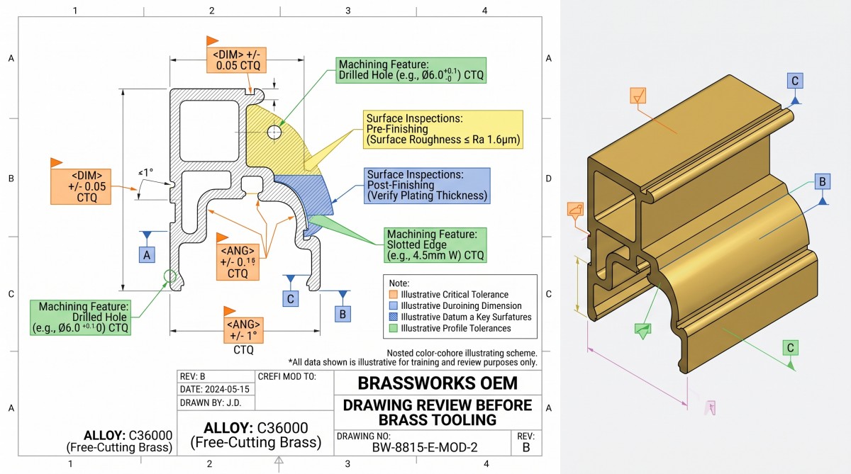
That is how an OEM project starts with a confident tooling quote and ends with a die correction, a rejected first article and a production delay. A drawing may show an H7 bore, a plated face, a 3 m cut length and every hole in the finished part. The extrusion die does not create all of those features. It creates a hot, continuous cross-section. Straightening, sawing, CNC machining, polishing, plating and inspection own the rest.
The costly question is not whether a shape looks extrudable. It is whether the drawing assigns every feature to the process that can reliably create it.
For a commercial starting point, review OEM custom brass extrusions. This guide addresses the decision before the RFQ becomes a die order: how to review the drawing, expose hidden process assumptions and calculate the cost of an accepted finished part.
Quick Answer: What Must Be Confirmed Before a New Die?
Before approving an OEM custom brass extrusion die, freeze the exact alloy, product standard and condition; provide a controlled 2D drawing plus usable CAD; classify the section as solid, open, semi-hollow or hollow; separate die-controlled geometry from straightening, cutting, CNC and finishing features; identify CTQs and datums; state whether each limit applies as-extruded or after processing; confirm machining allowance and inspection method; define die ownership and correction responsibility; and compare tooling against the total landed cost of accepted parts.
If one of those items is still a guess, the drawing is not ready for tooling.
Table of Contents
- OEM Custom Brass Extrusions: What the Drawing Package Must Contain
- Freeze the Alloy Before Freezing the Die
- Assign Each Feature to a Process Owner
- Screen the Section for Die Risk
- Choose Extrusion, CNC or a Hybrid Route
- Set Tolerances and Surface Requirements in the Correct Condition
- Control the Die Trial and First Article
- Calculate Tooling and Total Landed Cost
- OEM Brass Extrusion RFQ Checklist
- Common Drawing and Tooling Mistakes
- Frequently Asked Questions
OEM Custom Brass Extrusions: What the Drawing Package Must Contain
The die engineer needs a controlled manufacturing definition, not a screenshot, a product photograph or an outdated PDF attached to an email thread.
At minimum, send the latest revision of the following:
| Drawing or project item | Why the die and process teams need it | Red flag before tooling |
|---|---|---|
| 2D controlled section drawing | Defines walls, radii, slots, datums and CTQs | The section is copied from a catalog image or has no revision block |
| 3D STEP or equivalent CAD | Helps check profile continuity, interference and machining access | The 3D model and 2D section use different revisions |
| Alloy, standard and condition | Changes metal flow, strength, machining, finish and compliance | The request says only "brass" or uses a color name |
| Ordered length and release quantity | Determines straightening, cutting, packing and trial relevance | A short sample length is used to represent a long production length |
| Finished-part drawing | Identifies holes, threads, bores, datums and assembly interfaces | The extruded blank and finished part are shown on one layer with no states |
| Surface and finish map | Defines exposed faces, polishing, plating or coating sequence | "Bright," "mirror" or "class A" is the only finish instruction |
| Inspection and document plan | Defines MTC, FAI, dimensional reports and lot traceability | A material certificate is treated as proof of dimensional conformity |
| Annual demand and forecast | Supports route and tooling break-even analysis | The buyer asks for a die price without a realistic volume range |
Mark the manufacturing state beside each requirement: as-extruded, after straightening, after cutting, after CNC, after polishing/plating, or final assembled condition. A dimension without a state is open to interpretation.
The supplier also needs the use environment. A profile for a dry indoor guide, a high-cycle electrical component and a corrosive-water fitting may share a general shape but require different alloy, surface, documentation and inspection decisions. Do not make the die team infer the application from a part number.
Freeze the Alloy Before Freezing the Die
An alloy substitution after die approval is a new technical review, not a clerical change.
Brass grades differ in chemical limits, hot-working response, machinability, strength, corrosion behavior, surface color and regulatory exposure. The brass alloy product range is a useful category reference, but the RFQ still needs the exact UNS, EN or GB designation, product standard and condition.
| Common discussion point | What buyers may want from it | What must be verified before tooling |
|---|---|---|
| C26000 / CuZn30 | Forming response, appearance and general brass applications | Exact product form, extrusion feasibility, condition and finish requirement |
| C36000 free-machining brass | Repeated drilling, turning or milling with good chip control | Lead restrictions, customer-market rules and whether the proposed section is practical as an extrusion |
| C37700 forging brass | Forged or machined hardware applications | Do not assume a forging-oriented grade is the right continuous profile alloy |
| C38500 architectural bronze | Machinability and architectural finish discussions | The commercial name does not replace UNS grade, governing standard, condition or compliance limits |
These are not automatic equivalents. C26000 is commonly described as nominal 70/30 brass, while H62 is approximately CuZn38. C36000 and C38500 also carry different chemistry and application assumptions. Compare the chemical limits, mechanical requirements, product form and standard line by line before accepting a supplier's substitute.
Lead, RoHS, REACH, dezincification resistance and potable-water approval are separate requirements. A supplier may be able to discuss each one, but the buyer must name the applicable market rule and evidence in the drawing or purchase order. Do not write "lead-free" when the project actually needs a named limit or a specific approval.
Assign Each Feature to a Process Owner
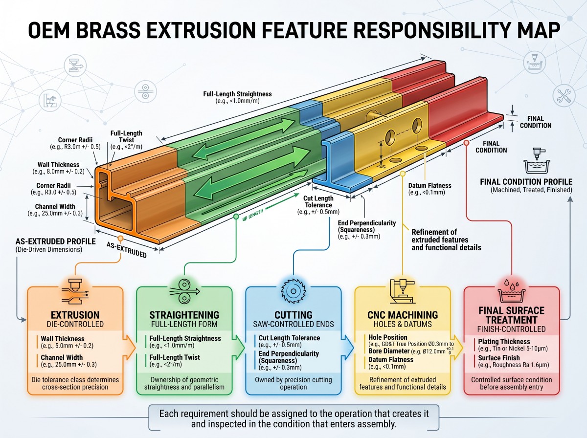
The most useful drawing review exercise is a process-ownership map. It turns a vague promise of "precision extrusion" into a sequence that can be quoted and inspected.
| Requirement | Primary process owner | State to inspect | Typical mistake |
|---|---|---|---|
| Alloy and condition | Material sourcing and extrusion route | Material received and linked to heat/lot | Treating a local grade name as an equivalent |
| Constant contour, walls and radii | Extrusion die and metal flow | As-extruded or sized state | Applying a machining tolerance to every profile dimension |
| Selected dimensional consistency | Drawing or sizing, when technically suitable | After the specified sizing operation | Prescribing cold drawing without a functional reason |
| Straightness, bow and twist | Cooling, stretching and straightening | Free state over a defined gauge length and ordered length | Approving a short coupon for a long profile |
| Cut length and end square | Sawing and deburring | Cut condition | Assigning saw tolerance to the die |
| Holes, threads, bores and datum relationships | CNC or another secondary operation | Final machined state | Expecting the extrusion die to create an H7 hole or true position |
| Polishing, plating or coating build | Surface-treatment process | Final surface condition | Measuring before finish when the part assembles after finish |
| Acceptance and traceability | Inspection and quality system | Agreed lot and report condition | Using an MTC as the only inspection record |
For a nominal 20 mm fit in the applicable 18-30 mm ISO 286 size range, an H7 hole is 20.000-20.021 mm and an h6 shaft is 19.987-20.000 mm. That example shows why a fit belongs to a controlled finishing operation and a defined datum scheme, not to a casual raw-extrusion promise. Confirm the applicable ISO edition and fit design for the actual component.
Screen the Section for Die Risk
A custom die follows metal flow. It does not simply trace the outside boundary of a CAD file.
Start by classifying the section as solid, open, semi-hollow or hollow. Then mark the features that can upset flow or die strength:
- Thin walls beside thick bosses
- Deep, narrow slots formed by slender die tongues
- Abrupt changes in wall thickness
- Sharp internal corners that could become functional radii
- Strongly asymmetric metal distribution around the section
- Hollow cavities that require bridges, ports or weld-line review
- Features that are intermittent rather than continuous along the length
- Faces that need machining stock but have no room at the tolerance extremes
For example, a 1.0 mm wall beside a 4.0 mm boss creates a 4:1 local thickness ratio. A 0.8 mm deep slot with a narrow tongue may also deserve a die-engineer review. Neither number is a universal rejection limit. They are prompts to ask for a drawing-specific flow and tool-strength assessment.
Ask the supplier to mark proposed radii, reliefs, bridge locations, bearing lengths and machining stock on the DFM response. If a feature cannot be made stable in the die, move it to sawing or CNC rather than forcing it into the cross-section.
The custom brass extrusion profiles page can help frame the commercial route. Examples of brass special-shape extrusions show why a similar-looking profile is not proof of identical flow, straightening behavior or die life.
Choose Extrusion, CNC or a Hybrid Route
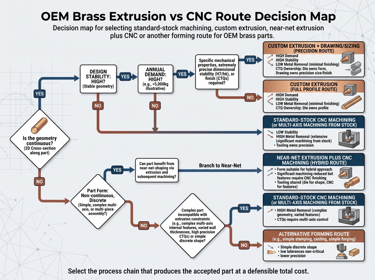
The best OEM route depends on section continuity, design stability, volume, material removal and accepted-part yield. It is not decided by the die price alone.
| Route | Best fit | Fixed commitment | Recurring cost or risk |
|---|---|---|---|
| Standard bar or plate plus CNC | Prototype, low volume or frequently changing design | Fixtures and programming | Excess metal, chips, cycle time and repeated setup |
| Custom extrusion plus cutting | Stable constant section and repeat demand | Die, trials and qualification | Conversion, straightening, crop and off-size material |
| Near-net extrusion plus local CNC | Repeated profile with holes, bores, threads or datums | Die, fixtures and qualification | Secondary machining and inspection still remain |
| Extrusion plus drawing or sizing | Suitable section needing a defined consistency or surface improvement | Multiple tools and process approval | Added processing, possible condition change and route limitations |
| Formed strip or forging plus machining | Thin open sections or discontinuous load-bearing bodies | Roll or forging tooling | Different finishing, machining and material-yield profile |
Use fine machining support or CNC machining services for brass as comparison points when the drawing contains many non-continuous features. A custom die is hard to justify when most of the extruded metal will be removed again.
The broader brass extrusion process guide is useful background, but it cannot qualify a new OEM section. Qualification belongs to the current alloy, CAD, tooling and ordered length.
Set Tolerances and Surface Requirements in the Correct Condition
"All dimensions +/-0.05 mm" is not a complete brass extrusion specification, especially when it applies across a metre-scale profile.
Separate the drawing into three tolerance families:
- General extrusion dimensions: walls, gaps, overall envelope and non-functional radii governed by an agreed product standard or supplier table.
- Long-length form: straightness, bow, camber and twist measured with stated support, gauge length, part temperature and free-state condition.
- Finished-part CTQs: holes, threads, bores, datum relationships, sealing faces and assembly interfaces controlled after machining or finishing.
Straightness must have a measurement method. A note such as 1.0 mm/m could mean a local limit over one metre, a cumulative limit over the full length or both. If a 3 m length is evaluated cumulatively, 1.0 mm/m is 3.0 mm of arithmetic allowance. That does not mean the profile is acceptable for a particular assembly; the drawing must define the actual functional limit.
Temperature also matters. ISO 1 uses 20 C as the standard reference temperature for dimensional measurement. Record part temperature, stabilization time, support condition and gauge method when limits become narrow.
Surface finish needs the same discipline. Ra alone does not control die lines, scratches, pits, waviness, gloss, grain direction or color. State which faces are visible, what finish route is used, how limit samples are approved and which defects are rejectable.
If a coating is 10 micrometres on each of two opposed faces, the theoretical outside dimension can increase by about 0.020 mm before process variation. Polishing removes material and can soften a corner. Mark whether the critical dimension is measured before or after the finish operation.
Do not insert a universal machining allowance into the drawing. A discussion value such as 0.30 mm per face may be reasonable for one geometry, but the supplier must confirm stock at the minimum and maximum as-extruded condition, tool access, burr direction, clamping and distortion risk.
Control the Die Trial and First Article
A polished 300 mm coupon cannot prove a 3 m straightness or twist requirement.
Use defined approval gates:
- DFM review and controlled drawing revision
- Die drawing approval with ownership and correction terms
- First extrusion trial using the specified alloy and condition
- Full-length first article at the ordered or representative length
- Dimensional, surface and material-document review
- CNC and finishing validation for all final CTQs
- Sample approval and production-release sign-off
If the die is corrected, record the die revision, affected dimensions, new trial scope and whether functional testing must be repeated. A correction that changes a slot, wall or datum relationship is not a cosmetic event.
Request evidence matched to the process boundary:
| Approval item | Evidence to request | Failure it prevents |
|---|---|---|
| Material identity | MTC linked to grade, condition, heat or lot | Uncontrolled alloy substitution |
| Die revision | Approved section drawing linked to die identification | Production from an obsolete revision |
| Cross-section | Measurements at agreed section locations | A few passing dimensions hiding wall drift |
| Long-length form | Straightness and twist report on representative length | Short coupon passing while assembly length fails |
| Machined CTQs | Datum-based dimensional report in final condition | Size passing while position or fit fails |
| Finish | Approved master or limit samples plus significant-face record | Plating, polishing or color mismatch |
| Traceability | Link among material, extrusion, machining and finish lots | Documents becoming detached from delivered parts |
Review the supplier's equipment and inspection capability as background evidence. Review quality certificates and inspection documents separately. Neither page replaces an order-specific MTC, first-article report or final lot inspection.
Calculate Tooling and Total Landed Cost
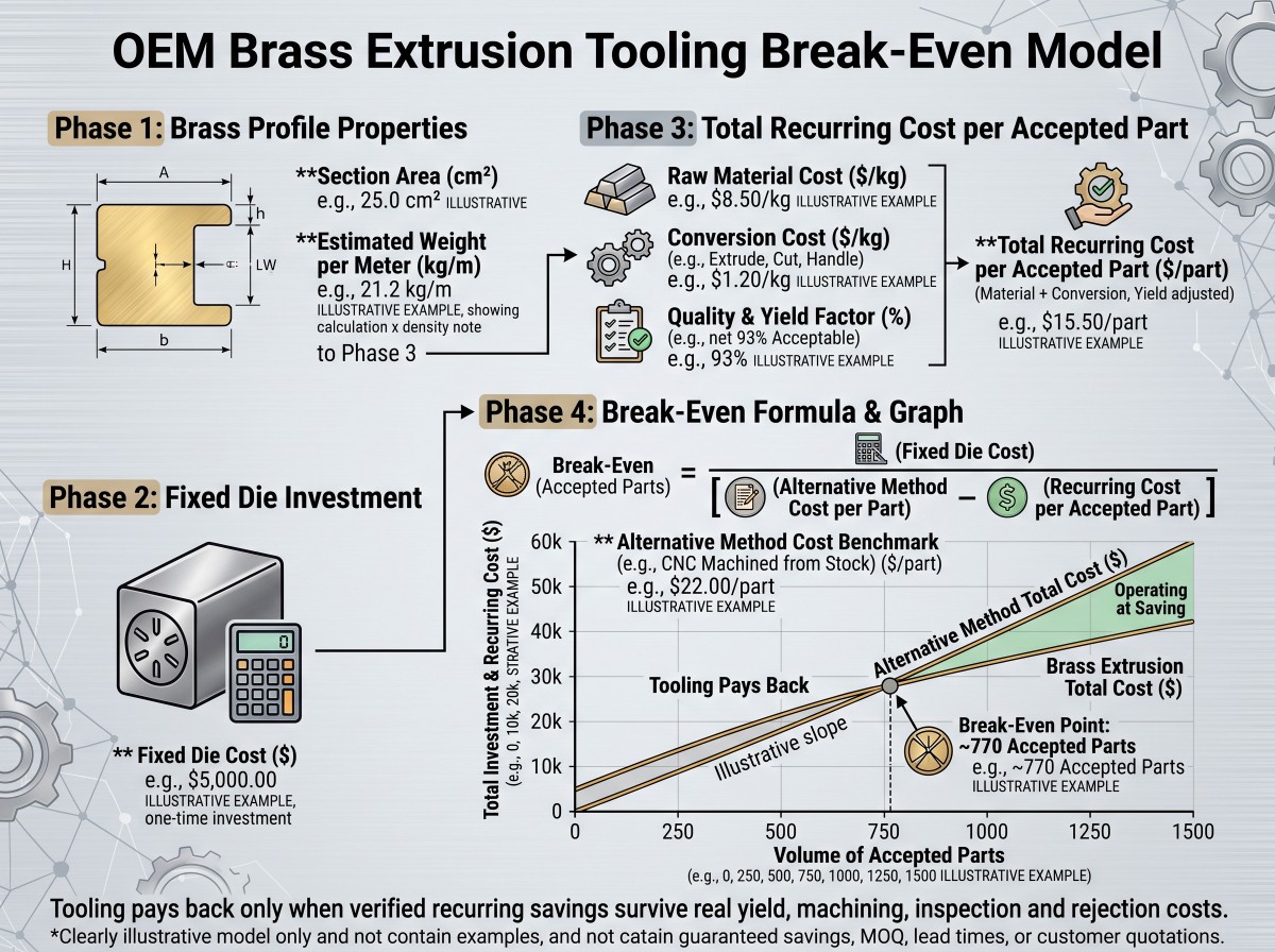
OEM buyers should compare cost per accepted part or accepted metre, not die price or metal price in isolation.
For a quick weight check, use:
Estimated kg/m = section area (mm2) x assumed density (g/cm3) / 1,000
With an illustrative area of 600 mm2 and an assumed brass density of 8.5 g/cm3, the theoretical mass is 5.10 kg/m. The actual grade, condition, crop, butt, saw loss and off-size recovery must be measured or quoted for the real program.
Landed cost per accepted part should include:
metal charge + die and qualification amortization + trial and scrap cost + extrusion conversion + straightening and cutting + CNC + finishing + inspection + packaging + freight and duty + expected rework, divided by accepted finished quantity
An illustrative break-even calculation is simple: a hypothetical $2,500 die and qualification package divided across 10,000 accepted parts adds $0.25 per accepted part. That number is meaningful only if the forecast is realistic and the denominator is accepted parts, not pieces started. If a drawing revision forces a new die before the forecast arrives, the arithmetic changes immediately.
For indexed brass buying, state the exact SMM series or the copper and zinc references, quotation or averaging dates, alloy or billet premium, payable metal content, currency conversion, chargeable weight and scrap-credit rule. "Market price at shipment" is not a comparable formula if one quote includes zinc and another does not.
The separate MOQ and tooling guide for brass profiles can support the commercial discussion. It does not replace a drawing-specific cost model.
For multi-stage programs, Cymber Metal's supply-chain service process provides context for coordinating material, extrusion, machining, finishing, inspection and export delivery. Actual scope, capacity, timing and documentation remain subject to the drawing and RFQ.
OEM Brass Extrusion RFQ Checklist
Send the following information so suppliers quote the same process boundary:
- Exact alloy designation, standard and condition
- Latest controlled 2D drawing and 3D CAD
- Solid, open, semi-hollow or hollow intent
- Section area, overall envelope, walls, slots and radii
- CTQs, datums, GD&T and non-critical reference dimensions
- As-extruded, straightened, machined and final-finish states
- Machining allowance and features to be added after extrusion
- Ordered cut length, release quantity and annual forecast
- Straightness, bow and twist limits with measurement method
- Saw-cut, end-square, burr and deburring requirements
- Surface finish, exposed-face map and approved limit samples
- MTC, FAI, PPAP-style, regulatory or third-party documents if required
- Lot definition, sampling plan and traceability records
- Die ownership, correction rounds, storage, maintenance and replacement terms
- Metal-price basis, conversion charge, kg/m control and scrap-credit logic
- Packaging, end protection, bundle support, destination and arrival target
In my experience reviewing OEM RFQs, the final-part drawing is often detailed enough to machine but not clear enough to purchase the extrusion. Add a one-page process map and ask the supplier to return a marked-up DFM review before you authorize tooling.
To start that review, contact Cymber Metal with the drawing and RFQ details. Ask for current material availability, tooling feasibility, sample scope, documentation and production timing for the actual project rather than assuming a generic website promise applies.
Common Drawing and Tooling Mistakes
1. Sending a screenshot instead of a controlled section
The die maker cannot reliably infer wall thickness, radii, hidden cavities or the active revision from a screenshot. Send a controlled 2D section and usable CAD.
2. Using "brass" as the alloy specification
Color and trade names do not define chemistry, condition, machinability or compliance. Name the grade and governing standard before DFM.
3. Putting H7, threads and every hole into the extrusion profile
The die creates a continuous section. Move local precision features to CNC unless the supplier's process review proves another route is practical.
4. Tightening every dimension to the same value
Blanket tight tolerances raise tooling, inspection and rejection risk while hiding the interfaces that actually control assembly. Mark CTQs and functional datums.
5. Approving a short sample for a long order
Short samples do not prove full-length straightness, twist, packing stability or shipping survival. Use a representative ordered length.
6. Leaving die ownership for the purchase order's fine print
State who owns the die, who pays for correction, where it is stored, when it may be used and what happens if the design changes or the program stops.
7. Comparing quotes by dollars per kilogram
The usable metric is cost per accepted finished part or metre after metal loss, machining, finishing, inspection, freight and rejection.
Bottom Line
OEM custom brass extrusions work when the drawing is treated as a process contract, not just a shape file.
Put constant geometry in the die. Put straightness and twist into a defined straightening and measurement plan. Put holes, threads, H7 fits and datum relationships into controlled secondary machining. Define the final surface condition, document requirements, die ownership and accepted-part economics before the first billet is heated.
Would you rather pay once for a justified die, or pay on every shipment for brass chips, rework and another correction trial? The answer comes from the drawing, the forecast and the accepted-part calculation.
Frequently Asked Questions
OEM custom brass extrusions are brass profiles produced to a customer's controlled drawing, usually with a substantially continuous cross-section and optional cutting, straightening, CNC machining or finishing. "OEM" does not define an alloy, tolerance or delivery promise. The RFQ must state the grade, standard, condition, geometry, final state, quantity and inspection requirements.
Usually, no. An extrusion die creates the continuous section and may leave material for a later operation. Holes, threads, counterbores, datum relationships and H7 fits are normally controlled by drilling, milling, broaching or CNC machining. Confirm the actual route against the drawing and final inspection method.
Send the latest controlled 2D section and finished-part drawing, a 3D STEP or equivalent model, alloy and standard, condition, ordered length, release quantity, annual forecast, CTQs, datums, surface requirements, machining scope, inspection plan and destination. Identify which dimensions apply as-extruded and which apply after machining or finishing.
No. Feasibility changes with alloy, section size, wall balance, open or hollow geometry, die design, press, ordered length and required tolerance. A thin wall beside a thick boss or a deep slot with a slender die tongue deserves a drawing-specific review. Ask the supplier to propose radii, reliefs and machining alternatives instead of relying on a universal rule.
Choose by function and governing specification, not color or a trade name. C36000 is often discussed for machining, C26000 for forming and general brass applications, and C38500 for architectural or finish-related work, but they are not automatic equivalents or universal extrusion choices. Compare chemistry, mechanical requirements, product form, corrosion and regulatory needs before tooling.
There is no safe universal value. A discussion value such as 0.30 mm per face may be suitable for one part, but the supplier must confirm it against as-extruded variation, die correction, tool access, clamping and distortion. The drawing should show the minimum remaining stock at tolerance extremes and the final machining datum strategy.
It should represent the feature that matters. A short coupon can verify material and local cross-section, but it cannot prove an assembly-length straightness or twist requirement. If the product is ordered in 3 m lengths, agree on a representative full-length trial or a documented validation method before production release.
Use accepted finished quantity, not gross pieces started. Add die and qualification cost, trials, conversion, straightening, cutting, CNC, finishing, inspection, packaging, freight, duty, rework and rejected material. Divide the fixed cost by the realistic accepted-part forecast, then test the result against design-change risk and actual annual releases.
Requirements vary by customer and market, but a typical package may include an MTC linked to heat or lot, first-article dimensional report, final inspection report, drawing and die revision, surface-treatment record, traceability across processing lots and any specifically required regulatory or third-party documents. Name each required document in the purchase order.
Post time: Aug-26-2026