
How Buyers Should Choose Between Extrusion, Drawing and CNC Machining
Publication Date: August 22, 2026
Author: Hu Yanwei, Cymber Metal Technical Expert
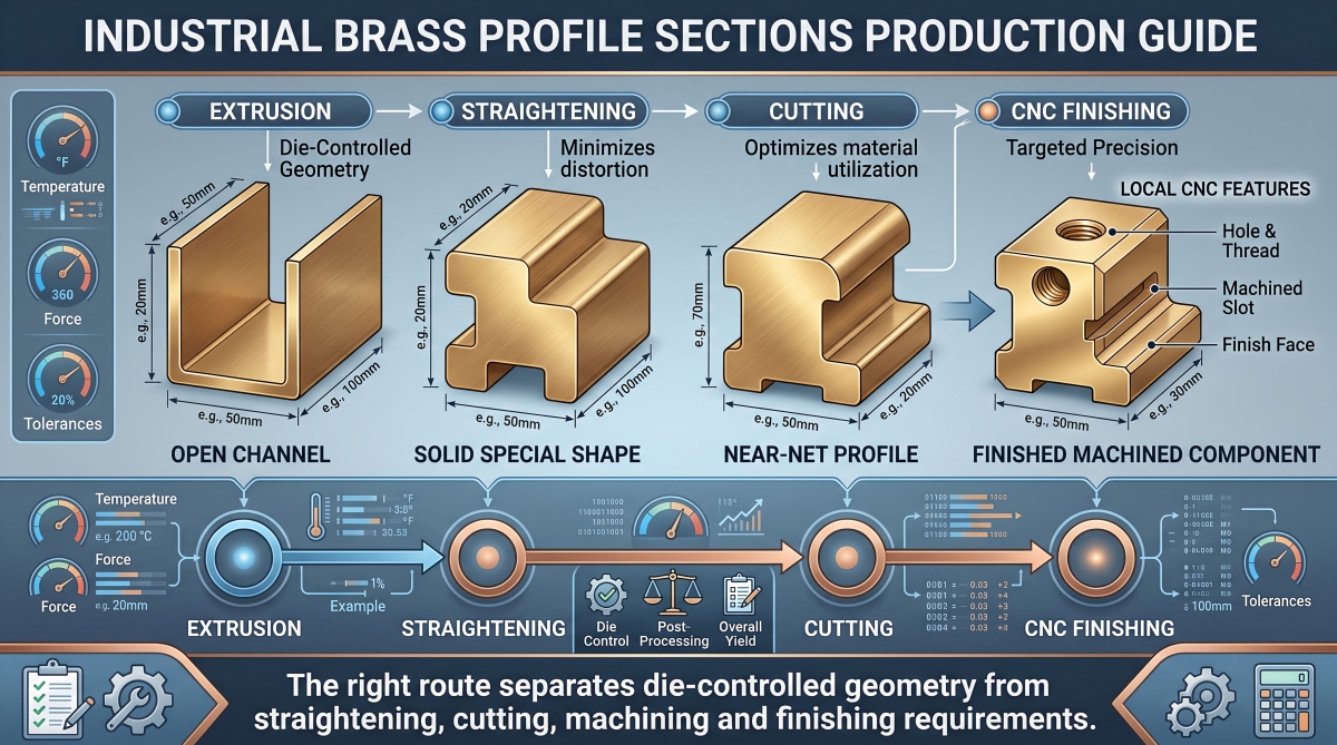
Do not approve a brass-profile die from the finished-part outline.
A common RFQ pattern is a drawing containing every hole, H7 bore, plating thickness and assembly datum, followed by a request for the extruder to make the whole part “to drawing.” That is not a production plan. It is an invitation for the die maker, straightener, saw operator, machinist and inspector to assign tolerance ownership differently.
The expensive failure appears after the first trial. The cross-section is technically extrudable, but the locating slot cannot hold the requested fit, the thin wall twists during straightening, or the supplier leaves too little machining stock on the only datum that matters. Saving a few cents per kilogram has just created another die correction, another sample shipment and another lost production window.
Industrial brass profile sections should be purchased as a controlled process chain, not as a shape with a price per kilogram. The buyer must decide which geometry belongs in the extrusion, which dimensions need drawing or sizing, which features must be machined, and which requirements apply only after surface finishing.
Quick Answer: How Should Buyers Select the Production Route?
Choose the route by section continuity, design maturity, accepted-part volume, material removal, critical tolerances and final surface condition. Use standard bar or plate plus CNC for prototypes, unstable designs and low volumes. Use a custom extrusion when a stable constant cross-section can remove meaningful metal and machining time. Add cold drawing or sizing only when the geometry and alloy support it. Use extrusion plus CNC for local H7 fits, datum-related holes, sealing faces and other features that an extrusion die should not be expected to hold. Compare total landed cost per accepted part, not tool price or metal price alone.
Table of Contents
- What Are Industrial Brass Profile Sections?
- Assign Every Requirement to a Process
- Compare the Main Production Routes
- Tooling Decisions That Control Yield
- Set Tolerances by Function
- Choose the Alloy Before Freezing the Die
- Calculate Total Landed Cost
- Approve the Process Before Bulk Production
- Common Procurement Mistakes
- Industrial Brass Profile RFQ Checklist
- Frequently Asked Questions
What Are Industrial Brass Profile Sections?
Industrial brass profile sections are long products with a substantially constant cross-section, commonly produced by hot extrusion and then straightened, cut, drawn, machined or finished as the application requires.
The section may be solid, open, semi-hollow or hollow, but those classifications and feasible tooling routes should be confirmed with the extruder. A photograph of a U-channel does not tell the die engineer the internal radii, wall distribution, slot depth, ordered length or datum strategy.
The word “industrial” also does not define an alloy, standard or tolerance class. It describes the use context. A profile may become a valve component, electrical connector body, guide rail, locking element, heat-transfer component, instrument part or machined hardware blank. Each application rejects parts for different reasons.
For broader material and product-form context, review Cymber Metal’s brass material and product forms. For a custom order, the drawing still needs an exact alloy designation, governing product standard, condition, cross-section, length, tolerance and inspection plan.
Do not confuse a constant-section profile with every long brass part. A turned shaft made from round bar, a forged valve body and a bent strip channel may all be long or shaped, but they use different production economics and acceptance controls.
Assign Every Requirement to a Process
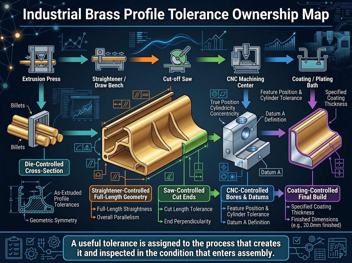
The fastest way to clean up an RFQ is to mark who creates and who verifies each feature.
| Requirement | Primary controlling operation | What the drawing or PO must state | Typical buying error |
|---|---|---|---|
| Alloy and condition | Material selection, melting and heat-treatment route | Exact designation, standard, condition and certificate requirement | Asking for “yellow brass” or assuming a local grade is automatically equivalent |
| Constant cross-section | Extrusion die and metal-flow control | Complete section CAD, critical dimensions, radii and machining allowance | Applying one tight tolerance to every wall, slot and boss |
| Section consistency | Extrusion plus optional drawing or sizing | Measurement locations and whether the requirement applies as-extruded or after sizing | Assuming cold drawing is available for every complex section |
| Straightness and twist | Cooling, stretching, straightening and cut length | Ordered length, support condition, gauge length and local or total limit | Approving a 300 mm coupon for a 3 m order |
| Cut length and end condition | Sawing and deburring | Length tolerance, squareness, burr and end-protection requirement | Treating saw tolerance as a die capability |
| Holes, pockets and precision fits | CNC, drilling, broaching or another secondary process | Functional datums, positional tolerance, fit class and inspection method | Expecting an extrusion die to produce an H7 bore |
| Plated or polished dimensions | Surface preparation and coating | Pre-finish and final-condition dimensions, significant surfaces and thickness | Measuring before plating when assembly occurs after plating |
| Final acceptance | Inspection and packaging | Lot definition, sample plan, reports, exposed faces and packing | Using a material certificate as proof of dimensional conformity |
This ownership map matters because tolerance has a cost only when it is tied to the operation capable of producing it.
A profile can have a generous non-functional outer contour and a locally machined interface controlled to a tight datum scheme. That is usually more stable than forcing precision into the entire extrusion.
Compare the Main Production Routes
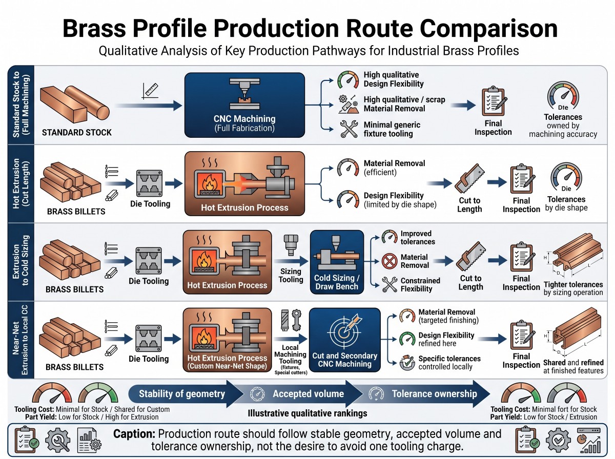
There is no serious route comparison without annual demand, part length, design stability and net section area.
Route 1: Standard Brass Stock Plus Full CNC Machining
Start with standard bar, plate or another available shape and machine away the unwanted material.
This route avoids custom extrusion tooling and responds quickly to design revisions. It is often the correct choice for prototypes, service parts, low volumes and geometries dominated by non-continuous features.
The commercial penalty is recurring. Every repeat order pays again for excess brass, spindle time, tools, chip handling, inspection and possibly distortion from asymmetric material removal.
Scrap credit may offset part of the metal loss, but it does not refund machine hours or late deliveries.
Route 2: Custom Hot Extrusion Plus Straightening and Cutting
A custom die forms a constant near-net cross-section. This can reduce purchased blank mass and repeated machining when the profile is stable and volume is sufficient.
It also introduces fixed cost, die-trial risk, minimum production economics and a new revision-control problem.
Custom brass extrusion profiles are most commercially persuasive when the section removes substantial recurring waste without putting local precision features into the die.
Route 3: Extrusion Plus Cold Drawing or Sizing
Cold drawing or another sizing operation can improve dimensional consistency, straightness or surface condition for suitable alloy, section and equipment combinations.
It may also change mechanical condition, add intermediate heat-treatment needs and require additional tooling.
Do not add “cold drawn” to an RFQ as a quality adjective. Ask what measurable requirement needs the operation and whether the proposed geometry can pass through that route without unacceptable distortion or tooling complexity.
Route 4: Near-Net Extrusion Plus Local CNC Machining
This hybrid route is frequently the practical answer for repeat industrial parts.
The die creates the mass-efficient constant section. CNC operations create holes, bores, threads, datum faces, sealing lands and local fits.
Cymber Metal’s fine machining support provides context for secondary processing, but actual fixtures, achievable tolerances, inspection frequency and batch capacity must be confirmed against the drawing.
Route 5: Formed Strip, Forging or Another Alternative
A thin, open channel may be more economical from formed strip than from a heavy extrusion. A discontinuous high-load body may suit forging plus machining. A simple rotational part may stay on the standard-bar route.
These are not inferior processes. They answer different geometry and volume conditions.
| Route | Strong use case | Main fixed commitment | Main recurring cost | Risk buyers often miss |
|---|---|---|---|---|
| Standard stock + CNC | Prototype, low volume, frequent revisions | Fixtures and programming | Excess metal and machining time | Cheap start, expensive repetition |
| Custom extrusion + cut | Stable constant section, repeated volume | Die, trials and qualification | Conversion, straightening and cutting | Cross-section may be feasible while full-length geometry is not |
| Extrusion + drawing or sizing | Compatible section needing better consistency | Extrusion and drawing tools | Extra processing and possible heat treatment | Assuming every hollow or asymmetric profile can be drawn |
| Near-net extrusion + CNC | Repeat parts with local precision features | Die, fixtures and qualification | Reduced machining plus secondary inspection | Too little machining stock after extrusion variation |
| Formed strip or forging | Thin open sections or discontinuous bodies | Roll-forming or forging tools | Route-specific finishing and machining | Comparing unlike products only by kilogram price |
For a broader process overview, see brass extrusion processes and profile options.
Treat its examples as background. The actual route must be qualified against the current alloy, CAD model and order conditions.
Tooling Decisions That Control Yield
A custom die does not merely copy the CAD boundary. It controls how hot metal divides, accelerates and exits around every wall, boss, groove and die tongue.
Deep narrow slots, weak die tongues, abrupt thick-to-thin transitions, sharp internal corners and strongly asymmetric mass distribution can make flow balance and die life harder.
A shape may be technically possible but commercially poor because correction rounds, low recovery or slow output overwhelm the theoretical material saving.
Ask these questions before releasing tooling:
- Which dimensions are genuinely die-controlled and critical?
- Can a sharp corner become a functional radius?
- Can wall distribution be made more balanced without changing assembly?
- Which faces need machining stock, and how much stock remains at tolerance extremes?
- Does a deep slot need extrusion, or can it be opened by sawing or CNC?
- How will the profile be gripped, stretched, straightened and gauged?
- What ordered length will be used during first-article inspection?
- Who owns the die, correction cost, maintenance records and replacement decision?
- What drawing revision is physically marked or linked to the die?
- What event triggers requalification after correction, repair or replacement?
Do not accept a universal minimum wall, radius or tongue ratio without reference to the actual alloy, circumscribing circle, press, section class and ordered length.
A supplier can provide design rules, but final feasibility belongs to a drawing-specific DFM review.
Examples of special-shape brass extrusions can help buyers discuss geometry, but an existing photograph does not qualify a new section. Similar appearance does not prove identical flow balance, straightening behavior or inspection access.
Tooling approval should have defined gates:
DFM release → controlled die drawing → first trial → correction if needed → full-length first article → final sample approval → production release
If the buyer skips the full-length trial to shorten qualification, the resulting twist or bow can cost far more than the trial freight.
Set Tolerances by Function
“All dimensions ±0.05 mm” is rarely a serious extrusion specification.
General cross-section tolerances should follow the governing product standard or an agreed supplier table. Critical characteristics should be identified separately, with measurement locations and final condition.
Standards such as ASTM B16/B16M for applicable free-cutting brass rod, bar and shapes or EN 12167 for applicable copper and copper-alloy profiles can provide a contractual framework.
Neither should be cited without confirming alloy, product form, condition, scope and current edition.
| Tolerance family | Example | Better control method |
|---|---|---|
| Cross-section size | Wall, channel gap, overall envelope and boss position | Mark CTQs on the section drawing; use an agreed standard for non-critical dimensions |
| Form within section | Flatness of a land, angle, contour or local concavity | Define measurement span, contact points and whether the surface is machined later |
| Long-length geometry | Straightness, bow, camber and twist | State ordered length, free-state support, gauge length, local limit and total limit |
| Cut condition | Cut length, end squareness and burr | Specify sawed condition, deburring and end inspection |
| Machined relationship | Hole position, bore size, thread and datum face | Use finished-part GD&T and inspect after machining |
| Final surface build | Plating or coating on opposed faces | State significant surfaces, thickness range and dimensions before and after finishing |
An H7/h6 fit makes the point.
For a nominal 20 mm fit in the applicable 18 to 30 mm ISO 286 size range:
- H7 hole: 20.000 to 20.021 mm
- h6 shaft: 19.987 to 20.000 mm
Those limits are appropriate for controlled finishing operations and inspection, not a casual promise on a raw hot-extruded opening. Verify the applicable ISO edition and fit design for the component.
Temperature matters when dimensional limits become narrow. ISO 1 uses 20°C as the standard reference temperature for dimensional measurement.
A warm profile and a cool gauge can create a false argument when neither party records part temperature, stabilization time or measurement method.
Finishing changes size too. Plating builds material while polishing removes it, and neither process acts perfectly uniformly around edges, recesses and rack-contact areas.
The drawing must state which limit applies before finishing and which applies to the final assembled condition.
Straightness cannot be reduced to “0.5 mm/m” without interpretation.
Is that a local limit over any one metre, a cumulative limit over the full ordered length, or both? How is the section supported? Which surface is the datum?
Twist must also have its own angular or gap-based method. A profile can be straight along one edge while its functional face rotates out of assembly.
Choose the Alloy Before Freezing the Die
Changing alloy after die approval is not an administrative substitution.
It can change hot-working behavior, metal flow, strength, machining response, surface color, corrosion behavior and regulatory status.
| Buying requirement | Relevant material question | Production-route consequence |
|---|---|---|
| Repeated drilling, turning or milling | Can C36000 or another machining-oriented brass meet the functional and regulatory requirements? ASTM B16/B16M is commonly referenced for applicable C36000 rod, bar and shapes | Better chip control may favor standard stock or near-net extrusion plus CNC, but lead restrictions can rule out the route |
| Complex constant section with limited machining | Which extrudable alloy and condition meet strength, corrosion and finish requirements? | Alloy flow and hot-working behavior must be reviewed before die release; a geometry approved in one alloy is not automatically approved in another |
| Regulated or corrosive water service | What exact low-lead, DZR or market approval is required? | “Lead-free,” DZR, RoHS, REACH and potable-water approval are different requirements and can change both alloy selection and available product forms |
| Shape developed from sheet or strip | Is the cited alloy actually available and governed as an extrusion? | C26000 rolled-form availability does not prove that a proposed complex extrusion is feasible or economical |
Grade equivalence needs line-by-line review.
C26000 is commonly treated as a nominal 70/30 brass, or CuZn30. H62 is approximately CuZn38. They are not automatic equivalents.
Compare chemical limits, mechanical properties, product form, condition and governing standard before accepting a substitution.
The MTC should identify the delivered alloy and heat or lot. It does not prove that the profile meets dimensions, straightness, machining or finish requirements. Those need their own inspection evidence.
Calculate Total Landed Cost
The cheapest extrusion quote can lose money in three places:
- Poor metal recovery
- Repeated CNC time
- Rejected finished lengths
First, keep the metrics separate:
- As-extruded recovery = acceptable as-extruded profile mass ÷ billet charge mass
- Customer material utilization = net finished-part mass ÷ purchased blank mass
- Finished acceptance yield = accepted finished parts or length ÷ total presented for final inspection
These are not interchangeable percentages.
Billet butt, trial material, crop, saw kerf, off-size lengths, straightening trim, machining chips, finish rejects and final dimensional rejects occur at different process boundaries.
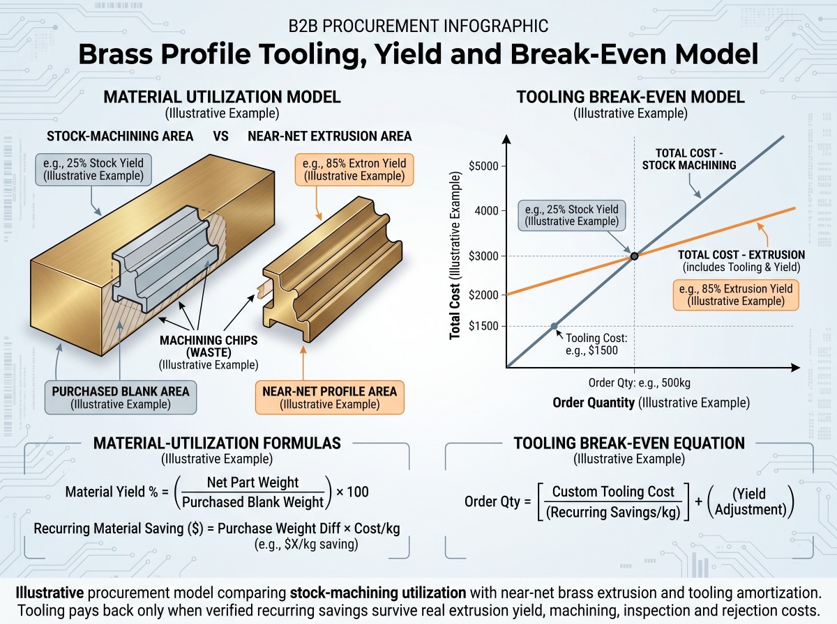
Consider a purely illustrative section calculation.
A finished part has a net cross-sectional area of 420 mm² and a length of 250 mm. Standard stock requires a 680 mm² blank, while a near-net extrusion requires 470 mm².
The part-level material utilization is:
- Standard-stock route: 420 ÷ 680 = 61.8%
- Near-net route: 420 ÷ 470 = 89.4%
Using an illustrative brass density of 8.4 g/cm³, the purchased blank masses are approximately:
- Standard-stock blank: 1.428 kg per part
- Near-net extrusion: 0.987 kg per part
- Difference: 0.441 kg per part
- Difference across 10,000 parts: 4,410 kg
That is not a guaranteed saving.
It excludes billet recovery, die trials, process scrap, saw loss, machining chips, scrap credit and acceptance yield. Use the certified alloy density or measured kg/m for the real quotation.
Tooling break-even is equally direct, provided both routes use the same accepted-part basis:
Break-even accepted quantity = (extrusion-route fixed cost − stock-route fixed cost) ÷ (stock-route recurring cost per accepted part − extrusion-route recurring cost per accepted part)
If a hypothetical die and qualification package adds $4,800 of fixed cost and the verified recurring saving is $3.60 per accepted part, simple payback occurs at 1,334 accepted parts after rounding up.
If recurring saving is zero or negative, there is no positive tooling payback.
If the $3.60 ignores finish rejects, inspection, freight, scrap ownership or die maintenance, the result is fiction with a calculator attached.
Build total landed cost on one dimensional basis:
Landed cost per accepted part = (total charged metal cost + route fixed cost + conversion, processing and logistics cost + expected rework cost − agreed scrap credit) ÷ accepted finished quantity
Convert every quoted element to the numerator before comparing routes.
Metal cost may be a rate per kilogram multiplied by chargeable weight. Tooling may be a fixed order or program cost. Machining may be quoted per part. Freight may be charged per shipment.
Use accepted finished quantity, not gross pieces started. Do not count the same yield loss twice if it is already embedded in the conversion or finished-part price.
For indexed buying, name:
- The exact SMM price series or exact LME copper and zinc references
- Quotation or averaging dates
- Payable metal-content logic
- Currency-conversion method
- Chargeable weight
- Alloy or billet premium
- Scrap-credit rule
- Whether conversion already includes any premium
“Market price at shipment” is not enough. It can omit zinc cost or count the alloy premium twice.
The detailed guide to tooling cost and bulk-order pricing expands this commercial calculation.
Approve the Process Before Bulk Production
A polished 200 mm sample does not approve a three-metre industrial profile.
First-article approval should represent the ordered material, route, length, machining and final condition.
If long-length straightness or twist matters, inspect the actual ordered length. If assembly occurs after plating, inspect the critical dimensions after plating.
If the die is corrected, identify whether the corrected revision needs dimensional reapproval, functional testing or both.
| Approval item | Evidence to request | Commercial failure it prevents |
|---|---|---|
| Material identity | MTC with grade, standard, condition, required test results and heat or lot; separate declarations, reports or approvals for named regulatory claims | Wrong alloy, unsupported equivalence or missing order-specific compliance evidence |
| Die and drawing revision | Approved section drawing linked to die identification | Production from obsolete geometry after an engineering change |
| Complete cross-section | First-article dimensional report at agreed locations | A few checked dimensions hiding wall or slot drift elsewhere |
| Full-length form | Straightness and twist results at the ordered length | Short samples passing while assembly-length profiles fail |
| Machined CTQs | Datum-based report in final machined condition | Local features passing size but failing position or assembly |
| Surface process | Significant-face map and thickness or appearance criteria | Plating build, polishing loss or rack marks changing acceptance |
| Process stability | Agreed sampling or capability study for named CTQs | A good first piece masking unstable batch variation |
| Traceability | Link among heat, extrusion lot, processing lot and inspection lot | Certificates becoming detached from delivered material |
| Packaging | Approved separation, end protection, bundle support and mass | Straight, clean profiles arriving scratched, stained or bent |
If the PO requires Cp or Cpk, define the CTQ, subgroup logic, sample size, calculation method and reaction plan.
A requested Cpk value such as 1.33 is not evidence until the process is stable, the measurement system is suitable and the data represent normal production.
Do not turn one trial batch into a capability claim.
Review machining and inspection equipment as supplier-background evidence. Review quality certificates and inspection documents separately.
Neither page replaces order-specific MTCs, first-article reports, gauge records or final lot inspection.
For multi-stage orders, the supply-chain service process can provide context for coordinating material, extrusion, secondary machining, surface treatment, inspection and export delivery.
Exact scope, capacity, timing and documentation still need project confirmation.
Common Procurement Mistakes
1. Choosing the Lowest Die Price
A cheap die that needs repeated correction, runs slowly or produces unstable wall distribution is not cheap.
Ask what is included in trials, corrections, sample lengths, dimensional reports, maintenance and replacement.
2. Tightening Every Dimension
Over-tolerancing raises tool risk and inspection cost while hiding the real CTQs.
Tighten the joint, datum or machining interface that controls function. Leave non-functional geometry at an agreed extrusion tolerance.
3. Approving a Short Coupon
A short section can prove alloy, local cross-section and finish direction.
It cannot prove full-order straightness, twist, packing stiffness or freight survival.
4. Changing Alloy After Tooling
The buyer saves time on a material review and loses it in another die trial.
Alloy substitution can change flow, die correction, machining, finish and compliance.
5. Comparing Price per Kilogram
Price per kilogram ignores kg/m drift, material utilization, machining cycle, finish rejection, inspection and accepted-part yield.
Compare cost per accepted part or usable accepted metre.
6. Leaving Die Ownership Undefined
When a program moves, pauses or changes supplier, unclear ownership creates a commercial fight.
Put ownership, storage, maintenance, use restrictions and disposition in writing before payment.
What to Put in an Industrial Brass Profile RFQ
Send enough information for each supplier to quote the same process boundary:
- Exact alloy designation, governing standard and required condition
- Controlled 2D section drawing plus 3D CAD where useful
- Units, radii, critical dimensions and non-critical reference dimensions
- Solid, open, semi-hollow or hollow intent, subject to supplier classification
- Ordered cut length, quantity per release, annual demand and program duration
- Net finished-part section area or weight where available
- Functional datums, CTQs and machining allowance at tolerance extremes
- Straightness, bow and twist limits with support and measurement method
- Saw-cut tolerance, end squareness, burr and end-finish requirement
- Cold drawing, heat treatment or condition requirement only where functionally justified
- CNC, drilling, broaching, deburring, bending or assembly scope
- Surface finish, significant faces, coating thickness and final-condition dimensions
- MTC, regulatory, FAI, PPAP, capability or third-party inspection requirements
- Lot definition, sampling plan and records to ship with the order
- Tool ownership, correction rounds, storage, maintenance and replacement terms
- Metal-price basis, conversion charge, kg/m control and scrap-credit logic
- Protective film, interleaving, end protection, bundle support and weight limit
- Destination country, Incoterm, arrival target and release schedule
In my experience reviewing RFQs, the drawing is often detailed enough to machine the final part but not clear enough to purchase the extrusion.
Add a one-page process map. Mark what is delivered as-extruded, what is machined, what is finished and what the receiving inspector will actually measure.
To review a new section, send your drawing and RFQ details with the alloy, standard, ordered length, annual quantity, critical dimensions, machining scope, surface condition, documents and destination.
Current material availability, tooling feasibility, MOQ, sample timing and production lead time must be confirmed for the actual order.
Bottom Line
Industrial brass profile sections are not automatically cheaper because they are near-net, and they are not automatically precise because a custom die is involved.
The right process puts constant geometry in the die, full-length form into straightening and measurement, local precision into CNC, and final-build dimensions after finishing.
It also prices every rejected metre, every machining cycle and every tooling correction into the accepted result.
Would you rather pay once for a justified tool, or pay on every shipment for brass chips and machine hours?
There is no universal answer. There is only a calculation based on a stable drawing, realistic yield and the production volume you will actually buy.
Frequently Asked Questions
Industrial brass profile sections are long brass products with a substantially constant cross-section, commonly produced by extrusion and then straightened, cut, drawn, machined or surface-finished.
The term does not define one alloy or tolerance. A purchase specification should state the exact grade, product standard, condition, section drawing, length, critical dimensions, final finish and inspection method.
The common route starts with a brass billet heated for extrusion, forced through a section die, cooled, stretched or straightened, cut and inspected.
Suitable profiles may receive cold drawing or sizing. Local bores, holes, threads and datum faces are normally added by secondary machining.
The exact route depends on alloy, section class, ordered length, tolerances and volume.
Choose custom extrusion when the design is stable, the section repeats along the part, and verified savings in purchased metal and machining exceed die, trial and qualification cost.
Keep standard stock plus CNC for prototypes, low demand or frequent revisions. Calculate break-even using accepted parts and realistic yield rather than gross production quantity.
No. Standard round, square, rectangular, hexagonal or available channel stock may satisfy the design.
A custom die is needed when the required constant cross-section is unavailable or when near-net geometry creates a valid recurring saving.
Confirm whether existing tooling is supplier-owned, customer-specific or actually compatible with the alloy and tolerances.
There is no universal brass-extrusion tolerance.
Capability changes with alloy, section size, wall distribution, open or hollow geometry, die design, ordered length, straightening, drawing, surface treatment and measurement method.
Use the governing product standard for general dimensions, identify CTQs separately, and ask the supplier to review the actual drawing before committing.
An extrusion may create a pilot opening or leave near-net material, but an H7 hole is normally finished and inspected by a controlled machining process.
For a nominal 20 mm hole in the applicable ISO 286 size range, H7 is 20.000 to 20.021 mm.
Confirm the standard edition, final surface condition, gauge method and datum relationship.
Extrusion creates the base cross-section by pushing heated metal through a die.
Cold drawing or sizing pulls a suitable profile through another tool to improve selected dimensional, surface or mechanical characteristics.
Drawing adds cost and is not feasible for every complex, asymmetric or hollow section. Specify the required result rather than prescribing drawing without a technical reason.
Divide the agreed fixed die, trial and qualification cost by the accepted quantity expected over a realistic program period.
Then add recurring conversion, machining, finishing, inspection, packing and logistics.
A low amortized tool value is meaningless if the forecast never arrives or if drawing changes force a replacement die before payback.
Requirements vary, but buyers commonly request an MTC linked to the heat or lot, first-article dimensional report, final inspection report, drawing and die revision, surface-treatment record where applicable, and traceability among extrusion and secondary-processing lots.
Regulatory or third-party documents must be named in the PO and verified for the destination market.
Provide the alloy and standard, condition, section drawing or CAD, ordered length, release quantity, annual demand, CTQs, straightness and twist method, machining scope, finish, certificates, inspection plan, packing, destination and schedule.
Also state die ownership and the commercial metal-price basis. Missing process boundaries produce quotations that cannot be compared fairly.
Post time: Aug-22-2026