
Publication Date: August 14, 2026
Author: Hu Yanwei, Cymber Metal Technical Expert
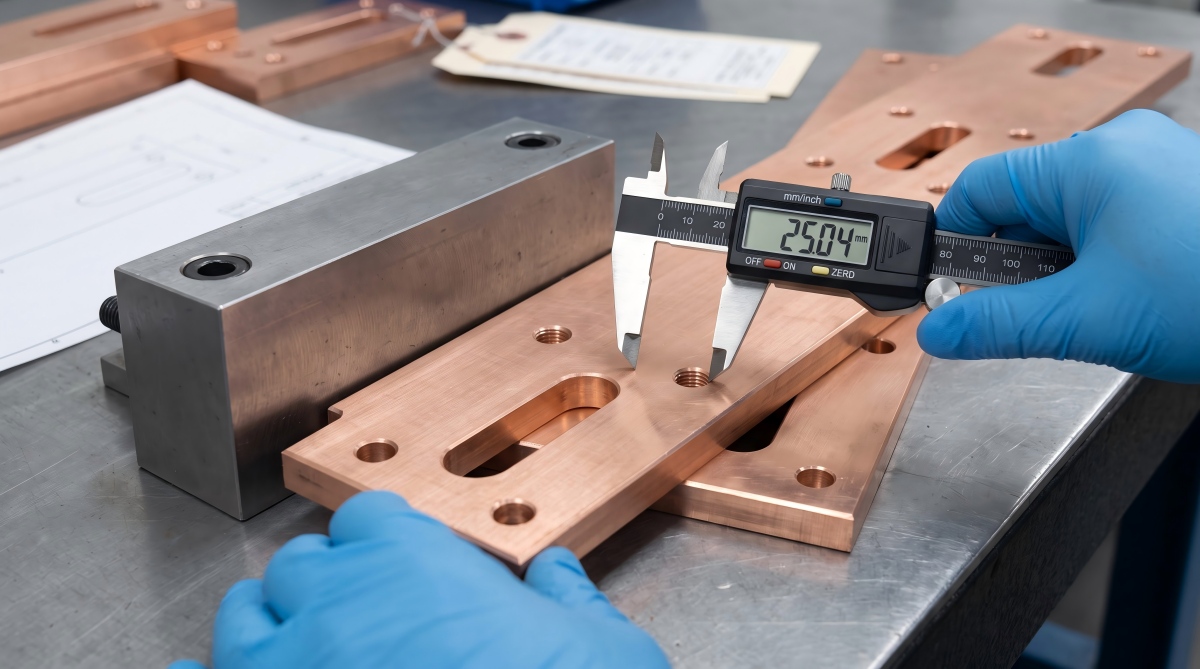
A copper busbar plate can arrive with the correct grade and conductivity report and still stop an assembly line.
The usual failure is painfully ordinary: every hole diameter passes inspection, but the pattern was measured from an unmachined edge, plating reduced the clearance, or the plate was clamped flat during inspection and sprang back after release. The purchasing team saved on the quotation. Production paid for hand reaming, rejected enclosures and an urgent replacement shipment.
That is the real job of copper busbar plate custom fabrication. It is not simply cutting copper and drilling holes. The supplier must convert electrical, mechanical and assembly requirements into a controlled material route, datum system, machining sequence, surface specification and inspection plan.
In this guide, the term means fabricating a current-carrying busbar from copper plate or rectangular bar. “Busbar plate” is not one globally standardized product form. A part purchased as plate and a part purchased as bus bar or rectangular bar can fall under different material standards and mill tolerances even when the finished drawings look similar.
Cymber Metal has a commercial page for copper busbar plate custom fabrication. This guide addresses the harder questions that should be settled before a drawing becomes a bulk purchase order.
Quick Answer: What Controls Custom Busbar Quality?
Reliable copper busbar plate custom fabrication depends on five controls: verified material and temper, a functional datum scheme, hole position rather than diameter alone, measurable edge and surface requirements, and an inspection plan matched to the manufacturing process. Plating, straightening, temperature and packaging must be included in the tolerance budget because each can change finished dimensions, flatness or assembly fit.
Do not ask one tolerance to solve every problem. Define which features carry current, locate the assembly, protect insulation, or exist only for clearance. Then spend machining and inspection money where failure would actually hurt.
Table of Contents
- Start With the Drawing, Not the Copper Price
- Material Form and Copper Grade
- Build a Functional Tolerance Stack
- Hole Accuracy and Process Selection
- Flatness and Measurement Temperature
- Surface Finish and Plating Sequence
- Inspection and Supplier Evidence
- Total Landed Cost
- RFQ Checklist
- Frequently Asked Questions
Start With the Drawing, Not the Copper Price
A low price per kilogram says nothing about whether a fabricated busbar will enter the cabinet without a drill.
In my experience reviewing RFQs, the most expensive drawings are not always the tightest. They are the drawings that make every dimension look critical while leaving the functional relationships unclear. A note saying “+/-0.05 mm unless otherwise specified” can force CNC machining and full inspection across the part, yet still fail to control the hole pattern relative to the mounting interface.
Before a supplier quotes, the drawing should answer four questions:
- Which face and edges establish datums A, B and C?
- Which holes locate the part, and which holes only provide bolt clearance?
- Do dimensions apply before or after plating, bending and straightening?
- Is flatness evaluated in the free state or while the part is restrained?
A website example of custom copper busbar fabrication for power cabinets shows the commercial product category. It does not replace a controlled drawing. Cabinet geometry, joint design, current, temperature rise, insulation clearance and mating hardware remain project-specific.
| Drawing omission | What the supplier may assume | What the buyer receives |
|---|---|---|
| No functional datums | Hole locations measured from convenient raw edges | Correct hole size, wrong assembled position |
| One tight tolerance on every dimension | Full machining and inspection whether needed or not | Higher conversion cost with no clear risk priority |
| No final-condition note | Dimensions checked before plating or bending | Parts that pass in process and fail at assembly |
| “Deburr all edges” only | Supplier-selected edge condition | Burr direction or sharp edge that damages insulation |
| Surface finish stated only as “bright” | Cosmetic polishing | Attractive part with uncontrolled contact behavior |
| No inspection method | Supplier chooses gauge and fixture | Buyer and supplier can measure different results |
Copper Busbar Plate Custom Fabrication Starts With Material Form
Plate, sheet, flat bar and pre-sized busbar stock are not interchangeable purchasing descriptions. Their thickness tolerance, edge condition, temper, residual stress, width control and applicable material standard can differ.
For many high-current components, buyers begin with C11000 electrolytic tough-pitch copper or C10200 oxygen-free copper. Neither grade should be selected from the word “pure” alone.
C11000 is widely used in electrical service. C10200 may be considered when oxygen-related processing behavior matters. C10100 can be relevant where a higher-purity oxygen-free electronic grade is justified. The correct choice depends on the governing standard, conductivity, forming, joining, atmosphere and certificate requirement.
At 20°C, 100% IACS corresponds to approximately 58 MS/m. That number is useful, but it does not prove flatness, hole location, contact resistance or finished-part quality. Specify the required minimum conductivity and test method rather than assuming every copper plate shares the same value.
For material context, review Cymber Metal’s pure copper busbar materials and copper plate options.
ASTM B187/B187M is commonly associated with copper bus bar, rod and shapes, while ASTM B152/B152M covers copper sheet, strip, plate and rolled bar. ASTM B248/B248M provides general requirements for wrought copper plate, sheet, strip and rolled bar.
In European specifications, EN 13601 may be relevant to copper rod, bar and wire for electrical purposes, while EN 13599 addresses plate, sheet and strip for electrical purposes.
The purchase order should identify one governing grade, standard, temper and form instead of treating different systems as automatically equivalent.
Do not calculate current rating from IACS and cross-sectional area alone. Allowable current and temperature rise also depend on AC or DC duty, ambient temperature, enclosure ventilation, skin and proximity effects, joint resistance, short-circuit forces and assembly geometry. Plating manages an interface; it should not be counted as useful copper current-carrying section.
| Material or form decision | Buyer benefit | Fabrication friction to check | RFQ detail |
|---|---|---|---|
| C11000 electrical copper | Familiar high-conductivity route for many busbar applications | Temper and oxygen-related joining limits must match the process | Alloy, standard, temper and minimum conductivity |
| C10200 oxygen-free copper | Low oxygen content for relevant processing or service requirements | Higher material cost may add no value if oxygen behavior is irrelevant | Alloy designation, product standard and certificate |
| Rolled plate | Practical for wide or non-standard profiles | Thickness, flatness and residual stress affect machining | Thickness tolerance, flatness and machining allowance |
| Flat bar or busbar stock | Efficient for repeated rectangular sections | Width and edge condition may limit datum choice | Width, thickness, edge radius and straightness |
| Soft or annealed condition | Easier bending and forming | Greater handling distortion and clamping sensitivity | Temper, bend route and final flatness condition |
| Harder temper | Better handling stiffness in some geometries | Higher forming force and possible springback | Temper, bend radii and mechanical-property limits |
For a broader electrical-material discussion, the article on electrical copper plate parameters for busbar assemblies covers conductivity, thickness and plate quality. This fabrication guide starts where the material certificate stops.
Build a Functional Tolerance Stack
Tolerances should follow the assembly function, not the buyer’s desire to make a drawing look precise.
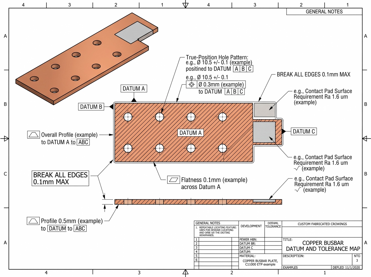
Use a stable datum scheme first. Datum A is often the main mounting or contact plane. Datums B and C may be machined edges, locating holes or other repeatable features. Raw sheared edges, rounded corners and flexible surfaces make poor datums unless the drawing deliberately defines how they are simulated.
Then divide dimensions into four levels:
- Critical-to-assembly features: locating holes, joint pads, mating steps and insulation interfaces.
- Electrical features: current-carrying cross-section, contact overlap and plated contact zones.
- General manufacturing features: outer profile, clearance holes and nonfunctional cutouts.
- Cosmetic features: appearance limits that do not control fit or current.
The values below are practical RFQ starting points, not universal acceptance limits and not Cymber Metal guarantees. Final tolerances depend on part size, copper temper, thickness, process route, plating sequence, quantity, datum scheme and inspection method, and must be confirmed against the drawing.
| Feature | Possible RFQ starting discussion | Why the buyer must qualify it |
|---|---|---|
| Laser- or waterjet-cut outside profile | +/-0.20 to +/-0.50 mm | Long parts, thick plate, kerf, taper, heat input and edge finishing change capability |
| CNC-machined datum edge or local step | +/-0.10 to +/-0.20 mm | Tighter values require stable fixturing, controlled temperature and a defined measurement setup |
| CNC-drilled clearance hole diameter | +/-0.05 to +/-0.10 mm | Drill size, exit burr, coating and gauge method affect the result |
| Laser-cut or punched clearance hole diameter | +/-0.10 to +/-0.25 mm | Thickness-to-hole ratio, die wear, taper and dross can dominate the result |
| Reamed locating hole | A fit class such as H7 only when function requires it | Hole size alone does not control position or mating-stack error |
| General assembly-hole pattern | True-position zone diameter 0.20 to 0.30 mm from defined datums | Large or flexible plates may need a different zone and restrained-state definition |
| Critical locating-hole pattern | True-position zone diameter 0.10 to 0.15 mm from defined datums | Diameter 0.05 mm or tighter is a high-cost feature requiring process-capability review |
| General CNC surface | Ra 3.2 micrometres maximum as an initial discussion point | Measurement direction and cutoff must be defined |
| Critical contact pad | Ra 1.6 micrometres maximum as an initial discussion point | Joint resistance also depends on flatness, oxide, plating, pressure and cleanliness |
| Critical hole or contact-zone burr | Maximum burr around 0.05 mm | Burr direction and inspection method must also be defined |
| General outside-edge burr | Maximum residual burr around 0.10 mm after a 0.2 to 0.5 mm x 45-degree chamfer, or R0.2 to R0.5 where specified | Insulation, creepage and mating faces may need a different limit |
| Local contact-pad flatness | 0.10 to 0.20 mm over a defined 100 mm pad; 0.05 to 0.10 mm for higher-demand discussion | Control only the functional pad and define support condition |
| Local free-state flatness of a long thin busbar | 0.20 to 0.50 mm within any defined 300 mm inspection span as an RFQ discussion point | Define the evaluation window and support condition, and specify a separate overall flatness limit across the full part length |
Do not pay for +/-0.05 mm on a decorative corner when the two locating holes are allowed to float from undefined edges. Apply tighter controls only to critical features, and give general dimensions a tolerance compatible with the selected cutting route.
Cymber Metal’s public copper CNC machining support provides process context. Each tolerance still requires a drawing review because a short 5 mm plate and a 1,500 mm flexible busbar do not behave like the same machining job.
Hole Accuracy Is More Than Hole Diameter
A bolt passing through a hole does not prove that the busbar fits correctly.
Hole diameter, positional tolerance, basic pitch, edge distance, countersink geometry and burr condition address different design concerns.
When hole-axis position is referenced to datum A, the positional tolerance also controls axis orientation. Add a separate perpendicularity control only when it serves an independent functional requirement.
A diameter gauge may confirm an 11.0 mm hole while the hole center is 0.8 mm away from the mating terminal. Both facts can be true.
Coordinate tolerances also behave differently from geometric tolerances. If a hole center is located by X +/-0.10 mm and Y +/-0.10 mm, its center can move anywhere inside a 0.20 x 0.20 mm square.
The maximum radial deviation at a corner is approximately 0.141 mm. A true-position zone of diameter 0.20 mm permits only 0.10 mm radial deviation. Those callouts are not equivalent.
For repeated hole patterns, use basic dimensions plus true position relative to A, B and C instead of stacking another set of +/- coordinate tolerances on the same relationship.
Maximum material condition may provide useful bonus tolerance for clearance holes under an ASME Y14.5-based drawing, but it should be used only when the engineering team understands the mating condition.
Use local flatness for a contact pad, parallelism to A for the opposing functional face, and profile for a controlled outside contour where appropriate. Under an ISO GPS drawing, apply ISO 1101, ISO 5459 and the declared specification principles consistently. Do not mix ASME and ISO symbol systems casually.
Choose the Hole Process From the Function
| Process | Best commercial use | Accuracy or quality friction | Batch economics |
|---|---|---|---|
| Punching | Repeated holes and profiles at stable volume | Rollover, die clearance, taper, burr direction and tool wear | Tooling cost can pay back at volume but is inefficient for changing designs |
| CNC drilling or milling | Mixed features, smaller batches and controlled hole patterns | Cycle time, chip control, exit burr and fixture movement | Flexible with no dedicated punch tool, but more machine time per part |
| Drilling plus reaming | Locating holes or defined fits | Requires stable pre-hole, alignment and suitable material support | Use only where the assembly needs fit-level diameter control |
| Fiber laser cutting | Rapid profile changes and nested sheet work | Copper reflectivity, heat input, dross and small-hole quality depend on equipment and thickness | Low dedicated tooling cost, efficient for prototypes and changing profiles |
| Abrasive waterjet | Profiles where low heat input matters | Kerf taper, edge roughness, abrasive residue and slower cycle | Useful for flexible geometry; finishing may still be required |
| Wire EDM | Complex or highly controlled profiles | Slow cutting and higher conversion cost | Reserve for critical features that justify it, not ordinary clearance holes |
The correct process can be mixed. Punch the general holes, CNC-finish the two locating holes, and machine only the critical contact step.
That hybrid route is often more economical than fully machining every feature or forcing a punch tool to hold a locating tolerance it was never designed to control.
Pure copper is soft and prone to built-up edge, smearing and pulled burrs. Sharp positive-rake tools, rigid but non-distorting fixturing, controlled chip evacuation and suitable cooling matter.
Excessive clamping force can flatten a thin plate on the machine and release bow after unclamping, producing the classic result: good on the machine, out of tolerance in the free state.
Cymber Metal’s public page for CNC, EDM and busbar processing equipment is useful during supplier review. The RFQ should still ask which exact process, fixture and inspection route are included in the quotation.
Design Clearance for the Real Assembly
Do not size a bolt-clearance hole at the nominal bolt diameter. Use the governing fastener and assembly standard, then calculate the available clearance against the complete stack:
- Busbar hole position
- Terminal hole position
- Enclosure tolerance
- Bracket movement
- Plating thickness
- Installation access
Slots can absorb stack-up, but their direction matters. A slot parallel to the wrong axis adds cost and solves nothing.
If two holes both lock the part without allowing thermal or manufacturing movement, the assembly can become over-constrained.
Define countersinks and counterbores from the required fastener seating condition. On soft copper, an aggressive countersink can deform under bolt load.
A thin residual section around a hole may also run hotter or distort during tightening. Electrical and mechanical design cannot be separated at the last drawing revision.
Flatness Can Be Lost After a Perfect Hole Pattern
Copper moves when material is removed, when a fixture is released and when temperature changes.
A supplier can clamp a bowed plate against a machine table, drill every hole accurately, and report excellent in-fixture results. Release the clamps and the plate may return to its free-state bow.
If the drawing never defined the inspection condition, both parties can defend their measurement.
Cutting, asymmetric pocketing, punching, bending, local polishing, straightening and plating can redistribute stress.
Adding an unapproved anneal to make the plate easier to flatten is not a harmless fix. It may change temper, strength, hardness and subsequent distortion. Process sequence belongs in the qualification plan.
Temperature matters as well.
Copper’s linear thermal expansion coefficient near room temperature is roughly 16.5 to 17.0 micrometres per metre per kelvin.
A 1,000 mm busbar measured 10°C away from the 20°C reference condition can differ in length by about 0.17 mm from temperature alone. That is already larger than some casually specified drawing tolerances.
For large or flexible busbar plates, state:
- Reference temperature or temperature-correction method
- Free-state or restrained-state measurement
- Support-point and fixture condition
- Overall flatness and local flatness, if both matter
- Whether plating, bending and straightening occur before final inspection
- Packaging support needed to preserve the accepted condition
A flat part can become a bent delivery if it is stacked against uneven separators, banded too tightly or allowed to slide in export packing.
Packaging is part of dimensional control, not an administrative line at the bottom of the purchase order.
Surface Finish Is Not a Cosmetic Checkbox
“Bright and smooth” is not an engineering surface specification.
A busbar plate normally contains several functional zones. Contact pads need controlled flatness, cleanliness and a surface route compatible with the joint. Insulated edges need burr and radius control. Plated areas need adhesion and thickness acceptance. Nonfunctional faces may only need sensible cosmetic limits.
| Surface zone | What should be controlled | What should not be assumed |
|---|---|---|
| Electrical contact pad | Flatness, roughness if relevant, cleanliness, plating, mask boundary and protection | A mirror finish automatically creates low contact resistance |
| Hole and slot edges | Burr direction, maximum burr or edge break, plating coverage and dimensional condition | “Deburred” means the same result to every supplier |
| Insulated edge | Radius or chamfer compatible with the insulation system | General cosmetic polishing prevents insulation damage |
| Plated non-contact area | Coating type, minimum local thickness, adhesion and appearance criteria | Any tin, silver or nickel thickness suits every temperature and atmosphere |
| Cosmetic face | Scratch, stain, fingerprint and color limits with an agreed visual standard | Cosmetic rejection criteria are obvious without a reference sample |
Surface roughness is one input, not a contact-resistance result.
Ra 1.6 micrometres may cost more than Ra 3.2 micrometres, but the smoother number does not overcome poor joint pressure, oxide, contamination, insufficient overlap, bolt relaxation or an unsuitable coating.
If Ra is specified, state the measurement direction, cutoff or evaluation length, and whether the requirement applies before or after plating.
Use Ra 0.8 micrometres or finer only when functional evidence justifies the added finishing and inspection cost. For critical joints, specify the joint design and validate resistance on the finished connection.
The following common coating bands are discussion points only, not recommendations or service-life guarantees:
| Coating route | Possible RFQ discussion band | What still must be defined |
|---|---|---|
| Electro-tin | 5 to 15 micrometres | ASTM B545 or another governing specification, minimum local thickness, maximum buildup, reflow if applicable, adhesion and mask zones |
| Engineering nickel | 5 to 15 micrometres | ASTM B689 or another governing specification, deposit class, significant surfaces, adhesion and corrosion requirement |
| Silver | 5 to 15 micrometres | ASTM B700 or another governing specification, minimum local thickness, anti-tarnish treatment, contact duty and wear cycle |
Application temperature, atmosphere, connection cycles, fretting, corrosion, solderability and contact design decide the coating.
A nominal or average thickness is not the same as a purchaser-specified minimum local thickness.
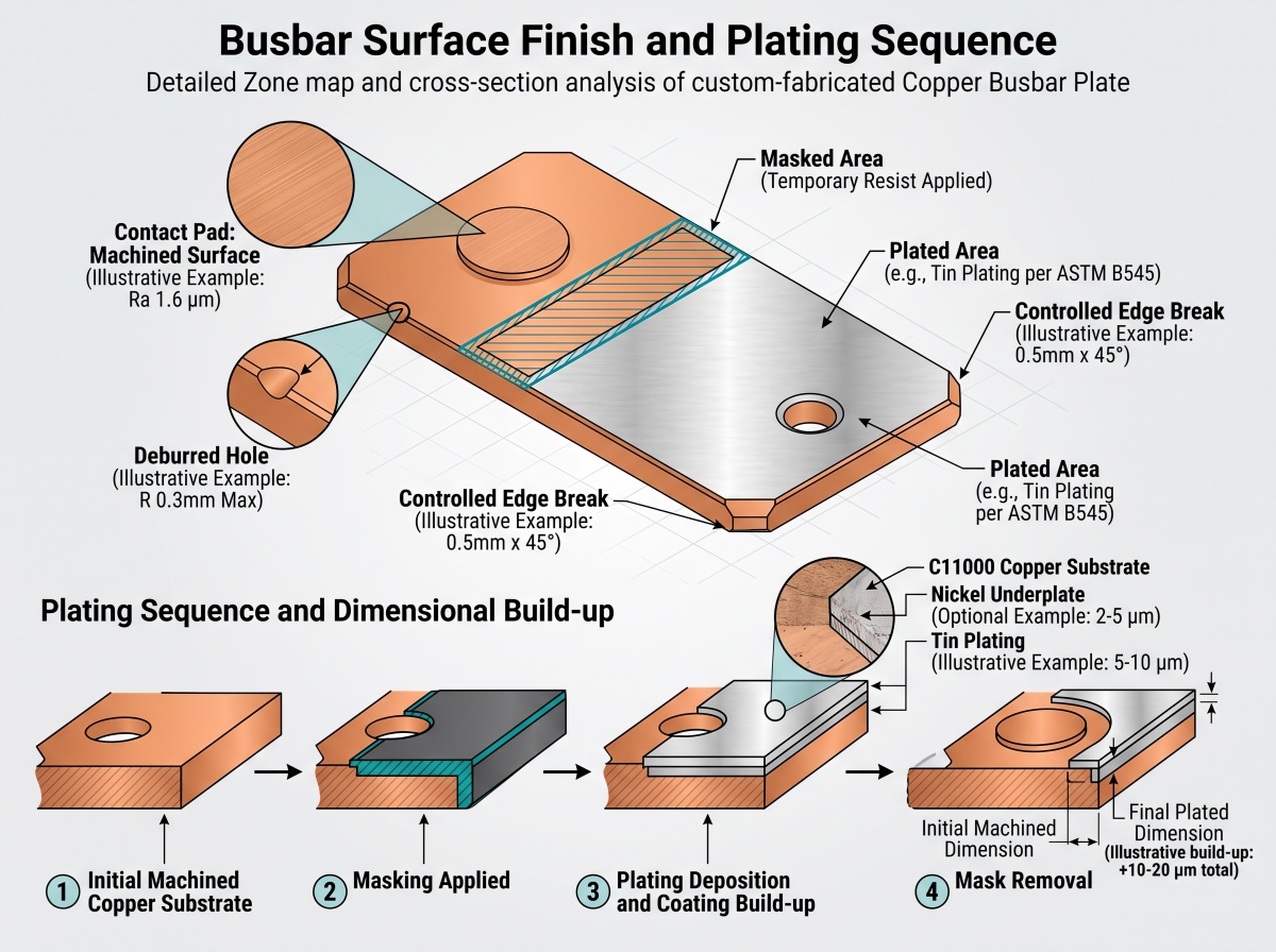
The plating decision also changes dimensions.
If 10 micrometres is deposited on each opposed surface, an outside dimension grows theoretically by about 0.020 mm.
If the hole wall receives 10 micrometres radially around the full circumference, the hole diameter shrinks theoretically by about 0.020 mm.
Critical fits must be checked against the permitted maximum local buildup, not only the nominal or minimum coating thickness.
Real electroplating distribution is not perfectly uniform: edges can build more, recesses can receive less, and rack or mask locations create local variation.
That is why the drawing must say whether critical dimensions apply before or after plating. It should also define significant surfaces, minimum local thickness, masking boundaries and whether hole walls require coverage.
For coating selection, review tin, silver and nickel busbar plating.
Tin, silver and nickel solve different interface, corrosion, temperature and wear problems. None should be described as a decorative upgrade that automatically improves the conductivity of the copper core.
Control the Machining and Plating Sequence
A practical starting sequence is:
- Verify material grade, temper, thickness and incoming condition.
- Cut the blank with enough allowance for critical datum features.
- Establish functional datums and machine the hole pattern, slots and local steps.
- Deburr and apply the drawing-approved edge condition.
- Complete drawing-approved bending where the selected route requires bending before plating, then recheck affected geometry.
- Clean the part without leaving polishing compound, coolant or adhesive residue.
- Mask and plate the specified surfaces.
- Inspect final dimensions, coating, surface condition and electrical features.
- Pack the finished parts to prevent abrasion, oxidation and distortion.
Machining after plating can expose bare copper at cut edges, threads and contact features.
Bending after plating can crack or thin a deposit that lacks sufficient ductility for the strain. Bending before plating can complicate racking and thickness distribution.
There is no universal sequence. The drawing and process plan must agree before production.
Inspection Must Match the Drawing
A material certificate proves material information. It does not prove that the finished hole pattern fits the assembly.
The inspection plan should follow a ballooned drawing and identify each critical characteristic, method, fixture, sampling rule and reporting requirement.
A prototype measured with a CMM does not automatically mean every production lot receives the same inspection.
| Inspection item | Suitable evidence or method | Main limitation |
|---|---|---|
| Material grade and temper | MTC linked to heat or lot | Does not confirm finished dimensions |
| Conductivity | Agreed resistivity or conductivity method, such as ASTM B193 or ASTM E1004 where applicable | Does not confirm joint resistance |
| Overall thickness and flatness | Calibrated thickness tools and surface-plate or CMM method with defined support | Clamping can hide free-state distortion |
| Hole diameter | Plug gauge, bore gauge, vision system or CMM | Diameter alone does not prove position |
| Hole true position and pitch | CMM or validated vision/fixture method relative to drawing datums | Results depend on datum simulation and fixture condition |
| Surface roughness | Calibrated profilometer with defined measurement direction and cutoff | Ra alone does not predict electrical contact performance |
| Burr and edge break | Optical measurement, comparator or agreed visual/tactile method | “No sharp edges” is not a numerical acceptance criterion |
| Coating thickness | XRF under ASTM B568 where suitable, cross-section or another agreed method at defined significant surfaces | One convenient reading can hide thin areas elsewhere |
| Coating adhesion | Agreed qualitative or quantitative method, with ASTM B571 as a possible reference | A visual pass alone may miss poor preparation or local separation |
| Finished-part resistance | Four-terminal Kelvin measurement between specified probe points at a defined test current and stabilized temperature | This is not an assembled-joint resistance test |
| Assembled-joint resistance | Four-terminal Kelvin measurement after assembly with specified mating surfaces, hardware, washer arrangement, torque or preload, dwell condition and temperature | Cannot be inferred from loose-part conductivity |
For a one-metre copper part, inspection temperature is not trivia. Record the part temperature, allow stabilization where necessary, and use the same reference condition when buyer and supplier compare results.
Supplier-level documents and order-level records must also be separated.
Cymber Metal’s quality certificates and inspection documents provide company and capability context. A bulk shipment still needs the specific MTC, dimensional report, coating report, first-article record or third-party inspection defined by the purchase order.
Do not write that a loose copper busbar plate is “IEC 61439 compliant” merely because it will enter a switchgear assembly.
IEC 61439 addresses low-voltage switchgear and controlgear assemblies and their verification. The busbar component must meet its drawing and material requirements, while the finished assembly remains responsible for the applicable system-level verification.
Supplier Selection: Ask for Process Evidence
The supplier should prove control of the route, not just show polished copper photographs.
Ask these questions before awarding a bulk order:
- Which material form, grade, standard and temper are included in the quotation?
- Which features are punched, laser-cut, drilled, milled, reamed or EDM processed?
- How are datums established and how is hole true position inspected?
- Are dimensions accepted before or after plating, bending and straightening?
- Which operations are subcontracted, and how are those suppliers controlled?
- Is a first-article inspection report included, and which characteristics are measured per lot?
- How are drawing revisions, tooling changes and process deviations approved?
- How will contact surfaces, edges and long plates be protected during export packing?
Cymber Metal’s public copper and aluminum supply-chain services page describes material selection, processing coordination, inspection and delivery support at a capability level.
The commercial quotation must still define the exact scope for the submitted drawing.
Beware of the supplier who answers every tolerance question with “no problem.”
A controlled answer sounds different: the supplier identifies the datum scheme, flags incompatible callouts, separates punched and machined features, explains the inspection fixture and asks which dimensions apply after plating.
Total Landed Cost Exposes the Cheap Quote
Busbar cost is not copper price plus a few drilled holes.
Use this model:
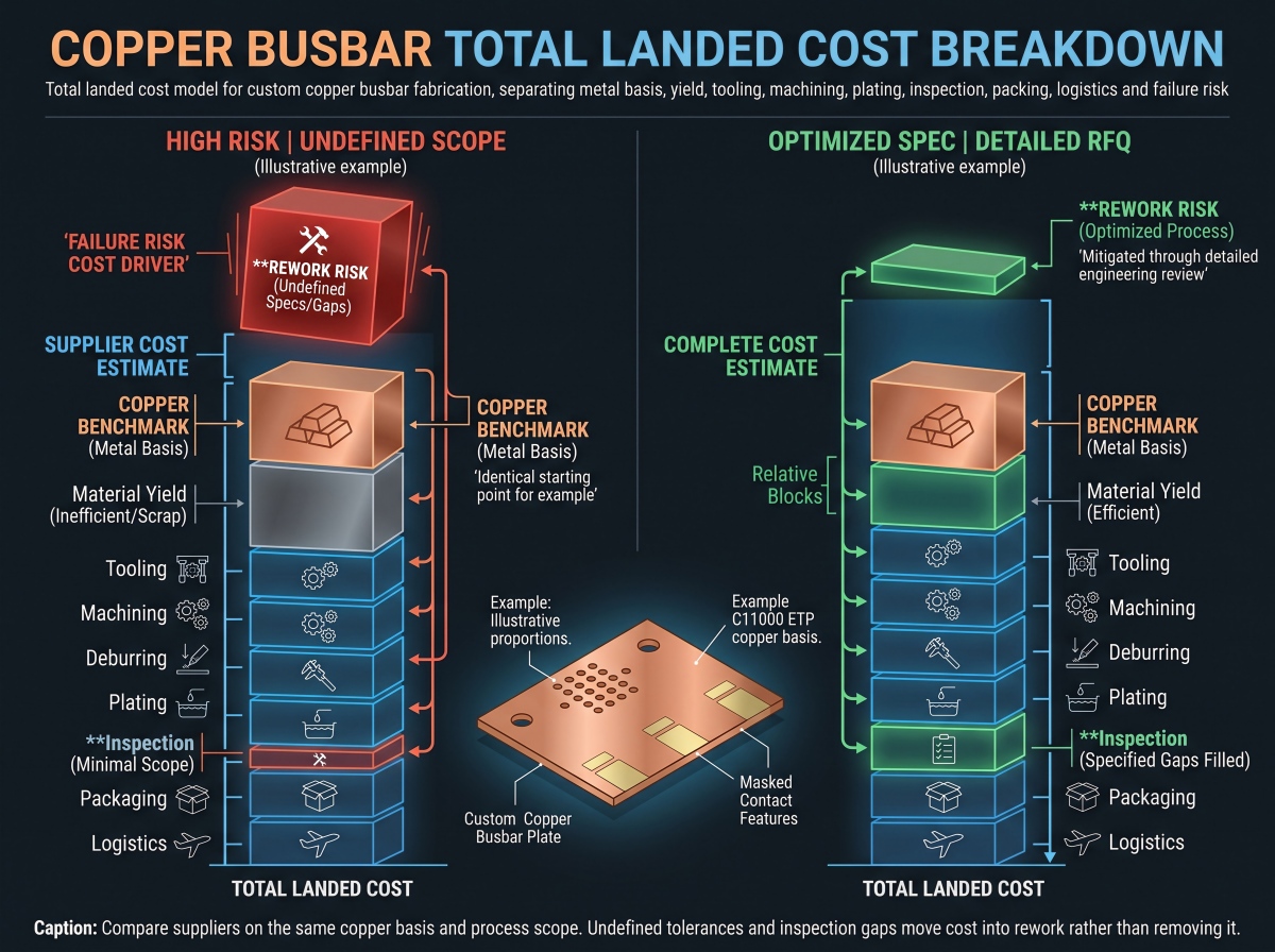
Total landed cost = metal basis + purchased-material yield loss + tooling + machining + deburring and cleaning + plating + inspection + packaging + freight and duty + rework risk
The metal portion should state the pricing basis.
For China-sourced orders, a quotation may reference an agreed SMM copper benchmark. Other contracts may use LME or a fixed copper basis.
The RFQ should define the reference, quotation date or averaging period, currency, conversion premium and whether the metal basis is locked or adjusted at order.
Do not compare two offers until both use the same metal logic.
Yield deserves equal attention.
A finished part weighing 8 kg may require more than 8 kg of purchased plate because of nesting gaps, kerf, edge allowance, clamping tabs and unusable remnants.
Scrap copper retains recovery value, but scrap credit does not erase machine time, working capital, sorting or the difference between purchased material and recovered scrap value.
Tooling and batch size change the best route.
A dedicated punch tool can be a bad decision for ten prototype parts that may change after testing.
Fully CNC-machining 20,000 stable parts can be equally wasteful if general holes and profiles can be punched reliably while only the locating features receive CNC finishing.
Inspection also has a real price.
Requiring CMM reports for every cosmetic edge consumes time without reducing electrical risk. Failing to inspect the two locating holes can shut down assembly.
The right plan concentrates 100% checks or tighter sampling on critical characteristics and uses an agreed lot plan for stable secondary features.
This is where cheap quotations become expensive.
A buyer saves a small conversion premium by accepting undefined hole position and pre-plating dimensions. The first lot arrives, M10 bolts enter some holes but not the complete stack, and operators hand-enlarge the pattern.
Now the buyer owns damaged plating, uncontrolled edge distance, extra labor, delayed panels and no clean root-cause record.
What to Put in a Copper Busbar Fabrication RFQ
Send enough information for every supplier to price the same finished condition:
- 2D PDF drawing, 3D model and drawing revision
- Material grade, product standard, temper and minimum conductivity
- Starting material form: plate, sheet, flat bar or busbar stock
- Overall dimensions, thickness tolerance, straightness and flatness
- Datum A, B and C definitions
- Critical hole diameters, true position, pitch, slots, threads, countersinks and counterbores
- General profile tolerance and critical-to-assembly dimensions
- Burr direction, maximum burr, edge break, chamfer or radius
- Contact-pad roughness, flatness, cleanliness and protection requirements
- Bare, tin, silver or nickel surface condition
- Coating process, minimum local thickness, significant surfaces and masking zones
- Statement that critical dimensions apply before or after plating and bending
- Quantity, prototype quantity, first-article requirement and annual usage
- MTC, conductivity, dimensional and coating reports
- Finished-part resistance report and/or assembled-joint resistance report, with the test setup defined
- Sampling plan, third-party inspection and change-control requirements
- Packing, destination country, Incoterm and required arrival date
Do not hide assembly conditions from the supplier and then expect the quotation to include them.
Share the mating drawing or at least the bolt, terminal, enclosure and insulation stack around each critical interface.
For a project-specific review, contact Cymber Metal for a busbar RFQ with the drawing, grade, critical features, surface treatment, quantity and inspection requirements.
Current material availability, processing feasibility, order quantity and delivery schedule should be confirmed against the actual specification rather than assumed from a website page.
Bottom Line
Custom busbar quality is decided before the first hole is drilled.
Choose the correct copper grade and material form. Establish datums from functional surfaces. Control hole position, not only diameter. Separate contact surfaces from cosmetic faces. Include plating and thermal expansion in the tolerance budget. Then make the inspection method match the drawing.
The expensive supplier is not always the one with the higher unit price.
It is often the one who leaves material yield, final dimensions, critical inspection and packing outside the quotation, then sends those costs back as rework and delay.
Frequently Asked Questions
There is no universal busbar tolerance.
Use a functional hierarchy: tighter control for locating holes, contact interfaces and mating steps; process-compatible general tolerances for outer profiles and clearance features.
Plate size, thickness, temper, machining route, plating and measurement condition affect feasibility. Send the complete drawing for a process-specific review rather than applying +/-0.05 mm to every dimension.
Define hole diameter, true position relative to functional datums, pitch, edge distance and any countersink or counterbore separately.
Diameter alone only proves that a fastener can enter the individual hole. It does not prove alignment with the terminal, enclosure or complete assembly stack.
State whether the acceptance dimensions apply before or after plating.
Not automatically.
Punching can be economical and repeatable for stable high-volume patterns, but tool wear, rollover, taper and burr direction require control.
CNC drilling or milling is more flexible and is often better for mixed features or critical hole patterns, but it adds cycle time.
A hybrid route can punch general holes and CNC-finish only locating features.
Yes.
If a coating of thickness t deposits uniformly on the complete hole wall, the hole diameter can theoretically decrease by about 2t, while an external dimension can grow by about 2t.
Actual electroplating distribution varies with geometry, current density, masking and throwing power. Critical dimensions must specify the final plated condition and measurement locations.
No single Ra value guarantees a low-resistance joint.
Ra 1.6 micrometres maximum for a more demanding machined contact pad, or Ra 3.2 micrometres maximum for a general machined pad, can serve as alternative RFQ starting limits.
State whether the limit applies before or after plating. Do not specify 1.6 to 3.2 micrometres as an acceptance band unless both an upper and lower bound are functionally required.
The final requirement also depends on flatness, coating, cleanliness, contact pressure, bolt system, overlap, temperature and validation method.
State the datum, support condition, free or restrained state, inspection method and reference temperature.
Thin or long copper plates may appear flat when clamped and recover bow after release.
If the assembly intentionally restrains the plate, define that fixture condition on the drawing. Otherwise, require free-state acceptance with an agreed surface-plate or CMM setup.
Neither is universally better.
C11000 is widely used for high-conductivity electrical components. C10200 is oxygen-free copper and may be justified where oxygen-related processing or service behavior matters.
Compare the applicable material standard, temper, conductivity, joining route, forming requirement, atmosphere and certificate.
Do not pay for a grade advantage the application does not use.
No.
An MTC supports the material grade, composition, temper or other reported properties for the linked heat or lot.
It does not prove hole position, flatness, burr control, roughness, coating thickness or assembly fit.
Bulk orders may also need a ballooned first-article report, dimensional inspection, plating records, traceability and final electrical testing where specified.
Request the MTC, drawing revision, first-article or dimensional report, critical-hole and flatness results, coating certificate and local thickness readings, conductivity report where required, final resistance data for critical joints, deviation approvals and lot traceability.
The exact package should be agreed before quotation because inspection scope affects both price and lead time.
Total landed cost includes the agreed copper basis, purchased-material yield, tooling, machining, deburring, cleaning, plating, inspection, packing, freight, duty and rework risk.
Compare suppliers on the same metal-pricing formula and finished scope.
A cheaper conversion price can be misleading when it excludes final plated dimensions, critical-hole inspection, material scrap logic or packaging that prevents distortion.
Post time: Aug-14-2026