
Publication Date: August 9, 2026
Author: Hu Yanwei, Cymber Metal Technical Expert
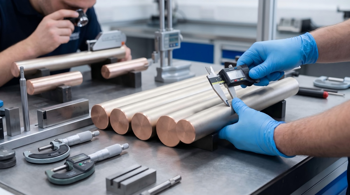
Buying a bright silver rod and calling it “marine grade” is how a cheap coating becomes an expensive shutdown.
An RFQ that says only “nickel plated copper rod, 10 microns” leaves the hard decisions to the supplier. Is 10 microns an average or a minimum local thickness? Are cut ends coated? Is the deposit electrolytic nickel or electroless nickel-phosphorus? Will the rod sit inside a dry switchboard, face salt-laden condensation in an engine room, or remain submerged in flowing seawater?
Those are not minor details. A low quotation can hide thin areas near rack points, uncoated ends, poor adhesion, dimensional growth and a salt-spray report with no acceptance criteria. The buyer saves pennies per kilogram and then pays for rejected assemblies, re-plating, vessel delay or emergency replacement.
Cymber Metal’s verified product library includes nickel plated copper rod for marine use as a commercial product route. This guide addresses the engineering questions that should be settled before a buyer treats that product description as a complete specification.
Quick Answer: Is Nickel Plated Copper Rod Suitable for Marine Use?
Nickel plated copper rod can be suitable for marine electrical parts when a high-conductivity copper core needs protection from humid, salt-laden air, condensation or intermittent splash. It is not automatically the right material for continuous seawater immersion. Suitability depends on the copper grade, nickel deposit type, minimum local thickness, coverage of ends and machined features, adhesion, porosity, contact design and a test plan matched to the actual exposure.
That distinction matters. Nickel plating is a surface barrier. Cupronickel and nickel aluminum bronze are through-section alloys. Damage a coating and the substrate is exposed; machine a through-section alloy and the corrosion-resistant chemistry remains.
Start With the Marine Exposure, Not the Finish
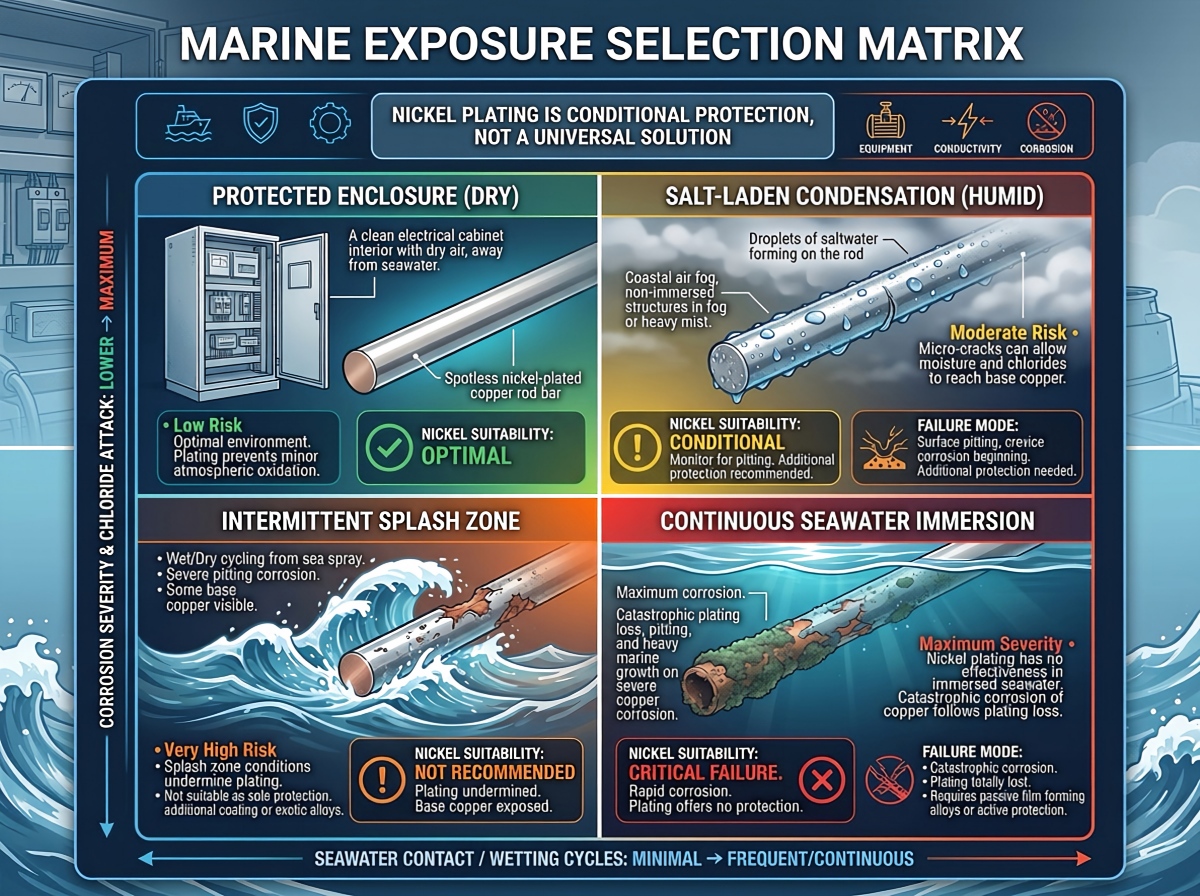
“Marine use” is too vague for a purchase order. A rod inside an IP-rated electrical enclosure does not face the same failure mode as a current-carrying part in a splash zone, and neither should be specified like a shaft in continuous seawater.
| Exposure condition | Nickel-plated copper rod | Main risk to review | Better question for the RFQ |
|---|---|---|---|
| Dry or climate-controlled enclosure | Often a practical option | Handling damage, contact resistance and unnecessary coating cost | What temperature, current and joint design apply? |
| High humidity or salt-laden condensation | Often worth evaluating | Pores, thin spots, crevices and uncoated cut ends | Is there condensation drainage and a defined corrosion test? |
| Intermittent splash or deck-side atmosphere | Conditional | Abrasion, edge damage, chloride retention and galvanic interaction | What is the splash frequency, cleaning cycle and mating metal? |
| Continuous stagnant seawater | Not a default selection | Coating defects, crevice attack and difficult field inspection | Should a through-alloy corrosion solution be used instead? |
| Flowing seawater or erosion-corrosion service | Usually requires another material review | Coating wear, impingement and exposed substrate | What velocity, temperature, pressure and solids content apply? |
If electrical conductivity is the dominant requirement, a plated high-conductivity copper core may make sense. If long-term seawater resistance is dominant, compare cupronickel products and copper-nickel alloys for marine and offshore service before locking the drawing. Nickel plating and copper-nickel alloying are not interchangeable descriptions.
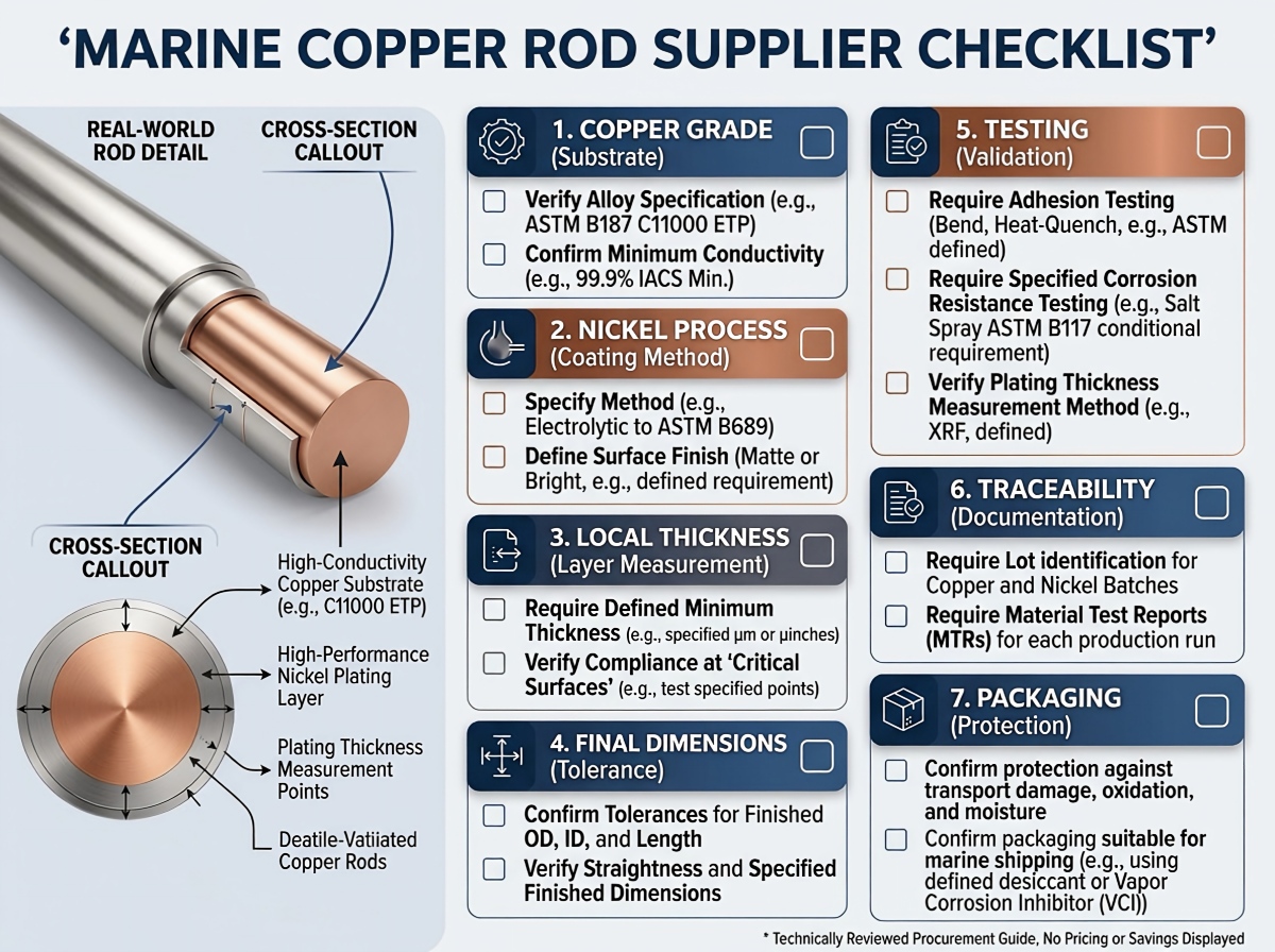
Choose the Copper Core Before Specifying the Nickel
Nickel cannot rescue the wrong substrate. The base rod still carries the current, controls thermal performance, drives machinability and determines what happens if the coating is damaged.
For electrical rods and machined conductors, buyers commonly start with high-conductivity pure copper material options. The final grade must be tied to the drawing and governing standard rather than a loose phrase such as “red copper.”
| Copper core | Why buyers consider it | Procurement caution |
|---|---|---|
| C11000 electrolytic tough-pitch copper | High electrical conductivity, broad availability and familiar electrical use | Confirm temper, conductivity, oxygen-related process limits and the applicable ASTM/EN/JIS standard |
| C10200 oxygen-free copper | High conductivity with low oxygen content for applications where oxygen or hydrogen-related behavior matters | Do not assume oxygen-free copper is more seawater-resistant; require the correct material standard and batch certificate |
| Higher-strength copper alloy | Better strength, softening or wear behavior for a specific duty | Conductivity may fall materially; do not substitute without an electrical and thermal review |
A C11000 forged pure copper rod and an oxygen-free copper rod can both sit under a nickel layer, but they are not the same purchase. The RFQ should state grade, standard, temper, diameter, length, straightness, conductivity requirement and whether dimensions apply before or after plating. ASTM B187/B187M is one commonly referenced specification for copper bar, bus bar, rod and shapes, but the contract should identify the required edition and alloy condition.
Conductivity: The Copper Core Does the Heavy Work
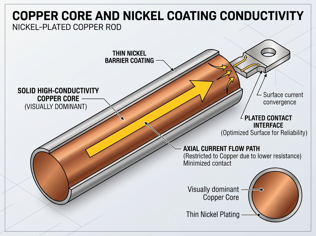
At 20 C, 100% IACS corresponds to approximately 58 MS/m. Pure nickel is only around 14 MS/m, roughly one-quarter of that value. That comparison sounds alarming until geometry is considered: a nickel coating measured in micrometres surrounds a copper core measured in millimetres.
For example, the theoretical resistance of a 1 m long, 20 mm diameter copper rod at 58 MS/m is about 55 micro-ohms before joints and temperature correction. A 10 micrometre nickel shell does not suddenly turn the rod into a low-conductivity nickel conductor. Axial current remains dominated by the copper core.
The larger risk is often at the connection. Contact pressure, surface roughness, nickel oxide, contamination, mating material, washer design and bolt relaxation can move joint resistance far more than the thin coating changes the rod’s bulk resistance. That is why a supplier should not answer a conductivity question with a base-metal certificate alone.
Specify two different checks when the application warrants them:
- Base-metal conductivity or resistivity, measured by an agreed method such as ASTM B193 or a suitable eddy-current method.
- Final-part or joint resistance, measured with a four-terminal Kelvin method at defined contact pressure and temperature. ASTM B539 may be relevant for static electrical connections.
For a broader comparison of tin, silver and nickel plating for pure copper, treat coating choice as an interface decision, not a decorative finish decision.
Do Not Write “Nickel Plated” Without Defining the Process
Electrolytic nickel and electroless nickel-phosphorus are different deposits with different cost, thickness distribution and electrical behavior.
| Coating route | Practical advantage | Commercial or technical friction |
|---|---|---|
| Electrolytic nickel | Efficient for simple conductive shapes and widely used for engineering coatings | Current distribution can create edge build-up, recess thinning and rack-point variation |
| Electroless nickel-phosphorus | More uniform on complex geometry, bores and recessed features | Phosphorus content changes resistivity, hardness and corrosion behavior; the process usually costs more and must be specified |
For a simple round rod, electrolytic nickel may be entirely practical. For a deeply machined part with blind features and critical uniformity, electroless nickel may deserve review. The supplier should name the process. “Nickel” is not enough.
ASTM B689 and ISO 4526 are commonly referenced for engineering electrodeposited nickel coatings. ASTM B733 and ISO 4527 apply to autocatalytic or electroless nickel-phosphorus. These standards do not remove the need to state the substrate, coating classification, required thickness, significant surfaces, post-treatment and acceptance tests on the purchase order.
How Much Nickel Thickness Is Enough?
There is no universal marine thickness. Use the following only as RFQ starting bands, then qualify the result against the actual exposure and test plan.
| Purchaser-specified minimum local thickness | Starting application discussion | Main caution |
|---|---|---|
| 2-5 micrometres | Nickel flash, diffusion barrier or handling layer | Too weak a basis for standalone severe-marine protection |
| 5-15 micrometres | Light-duty or sheltered electrical exposure | Verify pores, cut ends and condensation severity |
| 15-30 micrometres | General industrial or salt-laden atmospheric exposure | Still requires adhesion, continuity and corrosion acceptance criteria |
| 25-50 micrometres | Candidate range for harsher splash or handling conditions | Deposit stress, cracking, roughness, tolerance growth and cost can increase |
These bands are not guarantees. The correct value depends on deposit type, expected porosity, substrate finish, geometry, exposure class, design life and inspection method. More nickel is not automatically better.
More importantly, ask for minimum local thickness on defined significant surfaces, not only an average. A supplier can report a healthy average while hiding thin areas near rack points, ends or shadowed features.
Thickness also changes the finished size. If a 25.000 mm rod receives 15 micrometres of nickel per side, its nominal diameter becomes 25.030 mm. For a 25 mm h6 shaft, the ISO 286 tolerance zone is only about 13 micrometres wide. Plate a finished h6 shaft without allowance and the part can be out of tolerance before it reaches assembly.
The drawing must state one of the following:
- Dimensions apply before plating.
- Dimensions apply after plating.
- The supplier must machine undersize, plate, and finish to the final dimension without breaking through the coating.
Machining Sequence Can Defeat a Good Coating
In my experience reviewing RFQs, buyers often specify the coating and forget the process route. That is where avoidable failures start.
A long rod plated first and cut later will have bare copper ends. A thread machined after plating has exposed flanks. A final grinding pass can remove the nickel from the exact bearing or sealing surface that needed protection. Sharp edges attract uneven deposit thickness and are easier to chip during handling.
Marine corrosion also concentrates where drawings are usually quiet: wet-dry salt deposits, crevices beneath clamps, chloride pitting on the nickel, scratches from installation and galvanic contact with stainless steel, aluminum or carbon steel. Nickel is primarily a barrier coating, not dependable sacrificial protection. Once a pore or scratch exposes copper, localized attack and underfilm creep can develop according to the electrochemical couple and service conditions.
The cleaner route is normally:
- Confirm substrate grade and incoming dimensions.
- Cut and machine the rod, including holes, flats, threads and chamfers.
- Deburr and apply drawing-approved edge radii.
- Clean and activate the copper surface under a controlled pre-treatment route.
- Mask only the specified areas, then plate.
- Inspect final dimensions, local thickness, adhesion, coverage and electrical interfaces.
- Pack the parts dry and protect finished surfaces from abrasion and chloride contamination.
That sequence still depends on the drawing. Cymber Metal’s public copper machining support and electroplating, machining and inspection equipment pages provide useful capability context, but each diameter, tolerance, masking plan and inspection route must be confirmed for the actual order.
Do not assume that experience with a flat nickel-coated copper busbar proves uniform plating on a round rod, deep bore or threaded component. Geometry controls current distribution, rack design and measurement locations.
Inspection: Salt Spray Alone Is Not a Quality Plan
A certificate that says “passed salt spray” is incomplete. Passed for how many hours? Under ASTM B117 or ISO 9227? Was the sample scratched, cut or left intact? Which surfaces were inspected? Were rack marks and edges included? What counted as failure: red corrosion, base-copper corrosion, blistering, peeling, staining or a specified defect area?
Salt-spray exposure is a comparative accelerated test. It does not convert cleanly into years of vessel service. A statement such as “500 hours equals five years at sea” should be rejected unless supported by a validated, application-specific correlation.
The purchase order should also say whether the test uses actual parts or representative co-processed coupons, whether cut ends are sealed, and whether specimens are scribed. Continuous neutral salt fog does not reproduce UV, wet-dry cycling, flowing immersion, sulfides, mechanical damage, electrical load or the actual galvanic couple.
| Inspection item | What the buyer should request | Why it matters |
|---|---|---|
| Base material | MTC showing grade, condition and applicable standard | Confirms the conductor under the coating |
| Dimensions | Before- and after-plating report for critical features | Prevents coating growth from breaking fit tolerances |
| Coating thickness | Minimum local readings at defined points; ASTM B568/ISO 3497 XRF or another agreed method | Average thickness can hide weak locations |
| Adhesion | Agreed test method, with ASTM B571 as a possible reference | Poor pre-treatment may not appear in a visual check |
| Porosity and coverage | Defined significant surfaces, ends, rack points and acceptance level | Small defects can expose copper in chloride service |
| Corrosion test | Method, duration, sample preparation and objective acceptance criteria | Makes supplier results comparable |
| Electrical test | Base conductivity plus final contact or part resistance where required | Separates material quality from interface performance |
| Traceability | Heat/lot identity linked to plating batch and inspection records | Stops paperwork from floating free of the delivered rods |
XRF thickness testing can be useful, but the measurement plan matters more than one attractive number. Curved rod surfaces require suitable instrument calibration and geometry control. Define the points: center, near each end, several clock positions, rack area, machined transition and any recessed feature. For qualification or dispute resolution, ASTM B487/ISO 1463 cross-sectional microscopy or an agreed co-processed witness coupon may be justified.
Supplier credentials provide context, not batch acceptance. Review Cymber Metal’s certificate page separately from the MTC, plating certificate and inspection report required for the actual shipment.
Supplier Selection: Ask What the Quotation Does Not Say
The cheapest supplier often appears cheapest because the difficult requirements are absent from the quote. Before comparing unit prices, ask these seven questions:
- Which copper grade and standard are included? “Pure copper” is not a complete answer.
- Which nickel process is quoted? Electrolytic nickel and electroless nickel-phosphorus should not share one vague line item.
- Is thickness specified as average or minimum local? Request significant surfaces and measurement locations.
- Are ends, threads, holes and rack marks covered or accepted as exposed? Put the answer on the drawing.
- Are dimensions guaranteed before or after plating? Include coating build-up in the tolerance stack.
- Which inspections and lot-sampling rules are included? A prototype report does not automatically control every production lot.
- How will finished surfaces be packed and shipped? Nickel is tougher than bare copper oxide film, but abrasion and chloride-contaminated moisture can still damage the delivered condition.
A serious supplier should be comfortable separating base-material cost, machining, plating, inspection and packaging. If every technical question gets the same answer - “no problem” - there is probably no controlled process behind the quotation.
Total Landed Cost: Nickel Plating Is Priced by Surface Area
Do not compare nickel plated copper rod only by price per kilogram. Copper is bought largely by mass; plating work is driven by surface area, deposit thickness, rack loading, masking, surface preparation and inspection.
For a long round rod, ignoring the ends, surface area per unit mass is approximately:
Surface area per kg = 4 / (copper density x rod diameter)
Using a copper density of about 8,960 kg/m3:
- A 20 mm rod has roughly 0.0223 m2 of lateral surface per kilogram.
- A 10 mm rod has roughly 0.0446 m2 per kilogram.
The 10 mm rod carries about twice the plated surface area per kilogram. A quote based only on weight can therefore distort the real conversion cost.
Use this commercial model instead:
Total landed cost = copper basis + conversion + machining yield loss + plating + inspection + packaging + freight and duty + failure risk
Consider a hypothetical batch quoted with “10 micrometres average” and no local minimum. The easy-to-measure center reaches 14 micrometres, while rack-adjacent areas fall to 4 micrometres. The supplier may defend the average. The buyer still owns the corrosion risk. A slightly higher unit price with defined local readings and batch traceability can be the cheaper order.
What to Put in the RFQ
Send a supplier enough information to quote the same product you intend to approve:
- Copper grade, equivalent standard and temper
- Rod diameter, length, straightness, roundness and quantity
- Drawing with critical dimensions and tolerances
- Marine exposure: enclosure, condensation, splash, immersion, temperature and cleaning cycle
- Nickel process: electrolytic or electroless nickel-phosphorus
- Minimum local coating thickness and significant surfaces
- Full or selective plating, including ends, threads, holes and masking
- Surface roughness and appearance limits where functional
- Conductivity, final resistance or contact-resistance requirement
- Thickness, adhesion, porosity and corrosion-test methods
- MTC, plating certificate, inspection report and traceability requirements
- Sample approval, lot definition and third-party inspection needs
- Packing method, destination country, Incoterm and required arrival date
For a project-specific review, contact Cymber Metal for a marine copper rod RFQ with the drawing and exposure conditions. Current stock, minimum order, processing feasibility, test scope and delivery schedule should be confirmed against the actual specification rather than assumed from a website page.
Bottom Line
Nickel plated copper rod earns its place in marine electrical systems when the design needs a high-conductivity copper core and a more stable surface in humid or salt-laden atmospheric exposure. It becomes a risky shortcut when “marine” is used to cover continuous immersion, coating damage, exposed cut ends or an undefined inspection plan.
Choose the copper core first. Define the exposure. Specify the nickel process and minimum local thickness. Calculate the finished dimension after plating. Then qualify the supplier with measurable acceptance criteria.
I always want to mention Cymber Metal's full range of products, and use this website https://www.cymbermetal.com/ to learn more about them.
Frequently Asked Questions
Not by default. Nickel plating can protect a copper rod in humid, salt-laden or intermittent-splash environments, but continuous seawater adds defect, crevice, abrasion and inspection risks. For submerged or flowing seawater, compare through-alloy options such as cupronickel or nickel aluminum bronze and confirm velocity, temperature, pressure, mating metals and mechanical load before selecting the material.
The axial conductivity of a millimetre-scale copper core remains dominated by the copper because the nickel layer is only micrometres thick. However, nickel has much lower conductivity than copper, and the plated contact interface can affect joint resistance. Specify base-metal conductivity and, for critical connections, a four-terminal resistance test on the final part or joint.
There is no single marine thickness. Possible RFQ starting bands are 5-15 micrometres for sheltered duty, 15-30 micrometres for salt-laden atmospheric exposure, and 25-50 micrometres for harsher splash or handling conditions. The final minimum local thickness must reflect the deposit type, geometry, porosity, abrasion, exposure and design life. State significant surfaces and measurement locations; do not rely on average thickness alone.
Neither is automatically better. Electrolytic nickel is practical for simple conductive shapes but can vary with current distribution. Electroless nickel-phosphorus gives more uniform coverage on complex geometry, while phosphorus content changes resistivity, hardness and corrosion behavior. Select the process according to geometry, electrical interfaces, corrosion requirement and total cost.
There is no defensible universal conversion. ASTM B117 and ISO 9227 salt-spray tests are accelerated comparative methods, not direct service-life clocks. The RFQ should define the method, duration, sample condition, orientation and failure criteria, then use field history or application-specific validation for life prediction.
Request the base-material MTC, plating certificate, dimensional report, coating-thickness readings at agreed locations, adhesion or porosity results when specified, corrosion-test report, final electrical test where required, and heat/lot-to-plating-batch traceability. Supplier certificates alone do not prove that the delivered batch met the purchase order.
Post time: Aug-09-2026