
Publication Date: November 6, 2026
Author: Hu Yanwei, Cymber Metal Technical Expert
“Tin plated” is not a complete drawing requirement. Neither is “nickel plated.” If that is all your RFQ says, two suppliers can quote different coating systems and both believe they have met the specification. A useful copper busbar plating comparison starts with the joint, service environment and acceptance criteria, not the color of the finished bar.
Quick answer: Evaluate tin plating for qualified electrical-contact surfaces and normal indoor corrosion protection. Evaluate engineering nickel where defined wear, corrosion or other functional coating properties drive the specification. Neither is universally better. Buyers should define the copper substrate, complete coating stack, minimum local thickness, significant surfaces, finished dimensions and joint-validation requirements before comparing prices.
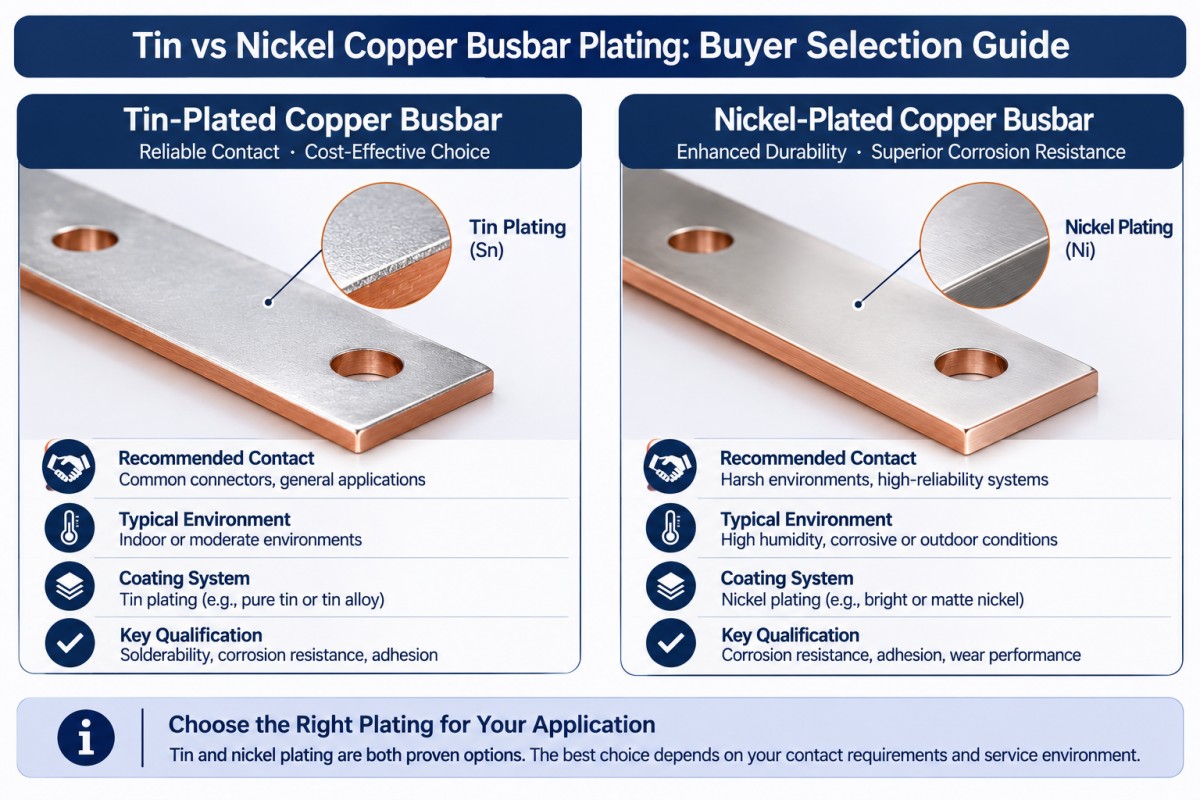
Tin vs Nickel Copper Busbar Plating: What Actually Changes?
The finish changes the surface system; it does not replace the conductor design. Copper grade, cross-section and operating conditions still need their own specifications. Start with the approved pure copper material options, then assess the coating and connection together.
| Buyer question | Tin-plated copper busbar | Nickel-plated copper busbar |
|---|---|---|
| Why evaluate this finish? | Tin coatings are used for electrical-contact surfaces, corrosion protection and solderability | Engineering nickel coatings are specified for functional properties including wear and corrosion resistance |
| What must the coating description say? | Deposition route, tin finish type, underplate if required, thickness and coverage | Electroplated nickel or electroless nickel-phosphorus, deposit requirements, thickness and coverage |
| What needs electrical validation? | Actual mating surface, assembly method and joint performance | Actual mating surface, assembly method and joint performance; hardness is not proof of lower contact resistance |
| What is a poor purchasing shortcut? | Assuming any shiny tin finish is suitable for the application | Assuming nickel automatically provides a higher assembly temperature rating or better joint performance |
ASTM B545 addresses electrodeposited tin coatings. ASTM B689 addresses electroplated engineering nickel coatings. They describe different coating systems, not interchangeable labels for a silver-colored surface. Neither standard alone establishes a complete busbar assembly’s current rating.
When Should Buyers Consider Tin-Plated Copper Busbars?
Specify the Contact Function, Not Just the Appearance
Tin coatings are used to provide low contact-resistance surfaces, but a coating designation does not guarantee the resistance of your assembled joint. State the mating terminal finish, contact geometry and approved assembly procedure.
For normal indoor exposure, ASTM B545 describes tin as protective on copper. It also warns that coating discontinuities can permit corrosion, particularly in humid conditions. Do not extend an indoor-use assumption to condensation, outdoor exposure or chemical service without review.
For tin-plated copper busbars for switchgear, identify the contact pads and explain whether the component is a bolted link, soldered connection or another qualified design. The acceptance plan should follow that function.
Do not turn a tin melting point into a continuous operating-temperature rating. The complete assembly needs its own thermal limits and validation.
Review Finish Type and Relevant Reliability Risks
If an approved specification distinguishes matte tin, bright tin or another permitted finish, preserve that distinction in the purchase order. Do not let a cosmetic preference silently change the coating process.
Tin whiskers also deserve application-specific review. NASA documents conductive whisker growth from tin finishes and the resulting short-circuit risk between closely spaced conductors. Where relevant to the equipment, ask the responsible engineer for the approved finish and mitigation requirements. That is a risk assessment, not a reason to reject every tin-plated power busbar.
When Should Buyers Consider Nickel-Plated Copper Busbars?
Define Which Nickel Process You Mean
Electroplated engineering nickel and electroless nickel-phosphorus are not the same coating. ASTM B733 covers the latter; its properties depend on phosphorus content and subsequent heat treatment. “Nickel plating” alone leaves too much open.
When reviewing nickel-coated copper busbar options, specify the approved process and required deposit properties. Ask the supplier to identify the proposed coating stack before accepting the quotation.
Validate the Contact Interface Separately
Engineering nickel becomes relevant when the drawing requires defined wear, load-bearing, corrosion or heat-scaling properties. Those requirements need a deposit-specific specification, not a blanket claim that nickel suits every harsh environment.
Wear resistance, corrosion behavior and electrical-contact performance are separate questions. A coating selected for one does not automatically satisfy the others.
Will the joint remain within the allowed resistance and temperature-rise limits after the specified duty cycle? Require evidence from representative joints using the actual mating finish, hardware and assembly conditions. Do not accept appearance or coating hardness as a substitute.
How Should Buyers Specify Busbar Plating Thickness?
Specify the required thickness on defined surfaces, with an agreed measurement and acceptance method. Avoid an isolated note such as “5 micrometers plating” that leaves the supplier guessing whether it means nominal thickness, a batch average or a minimum local value.
Define the Complete Stack and Significant Surfaces
For each layer, state material, required thickness or range, and where it applies. If a nickel underplate is required beneath tin, show it explicitly. Do not assume it is included, and do not introduce one without engineering approval.
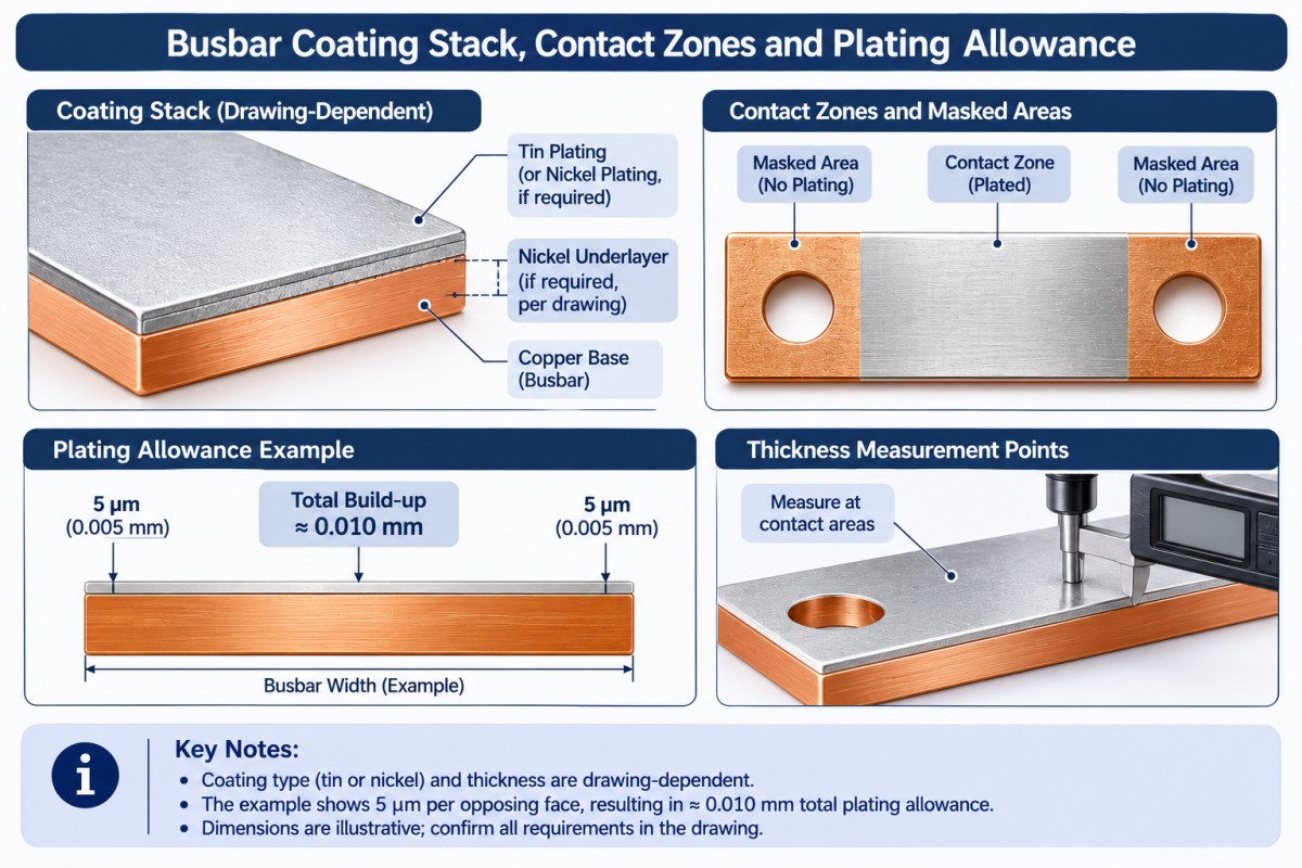
Mark contact pads, coated and masked zones, hole bores, threads, edges, and permitted rack-contact locations. Identify inspection points on the drawing. A reading on an easy-to-reach flat area should not stand in for an unmeasured critical contact region.
State Whether Dimensions Apply Before or After Plating
Consider an illustrative coating thickness of 5 micrometers on each opposing face. Uniform deposition adds approximately 0.010 mm to the overall dimension. The same ideal thickness on opposite sides of a hole would reduce its diameter by approximately 0.010 mm.
This is geometry, not a recommended thickness or a process-capability guarantee. Actual deposition and access must be reviewed. Nevertheless, it explains why a tight fit that passes before plating may fail afterward.
Use copper component machining review to agree on finished dimensions, machining allowance and process sequence. Do not discover the missing allowance during incoming inspection.
What Should Happen Before and After Plating?
Agree on the manufacturing sequence before releasing the order. A proposed route for finished fabricated parts is cutting, holemaking, deburring and forming, followed by cleaning, plating and final inspection. The actual route must match the drawing and coating requirements.
Preplated stock is a different route. If cutting or forming follows plating, explicitly address exposed cut edges, holes, bend areas and any required repair or recoating. “Made from plated copper” does not mean every finished surface is coated.
For custom copper busbar fabrication, identify operations that must be completed before final finishing. A new hole added after approval can create a coating-coverage issue as well as a drawing-change issue.
Define masking and rack-contact locations early. Where selective plating is allowed, show its boundaries. Review the proposed route against the busbar plating process information, but confirm feasibility for the actual part rather than assuming every geometry follows the same process.
Why Does Joint Validation Matter More Than a Shiny Finish?
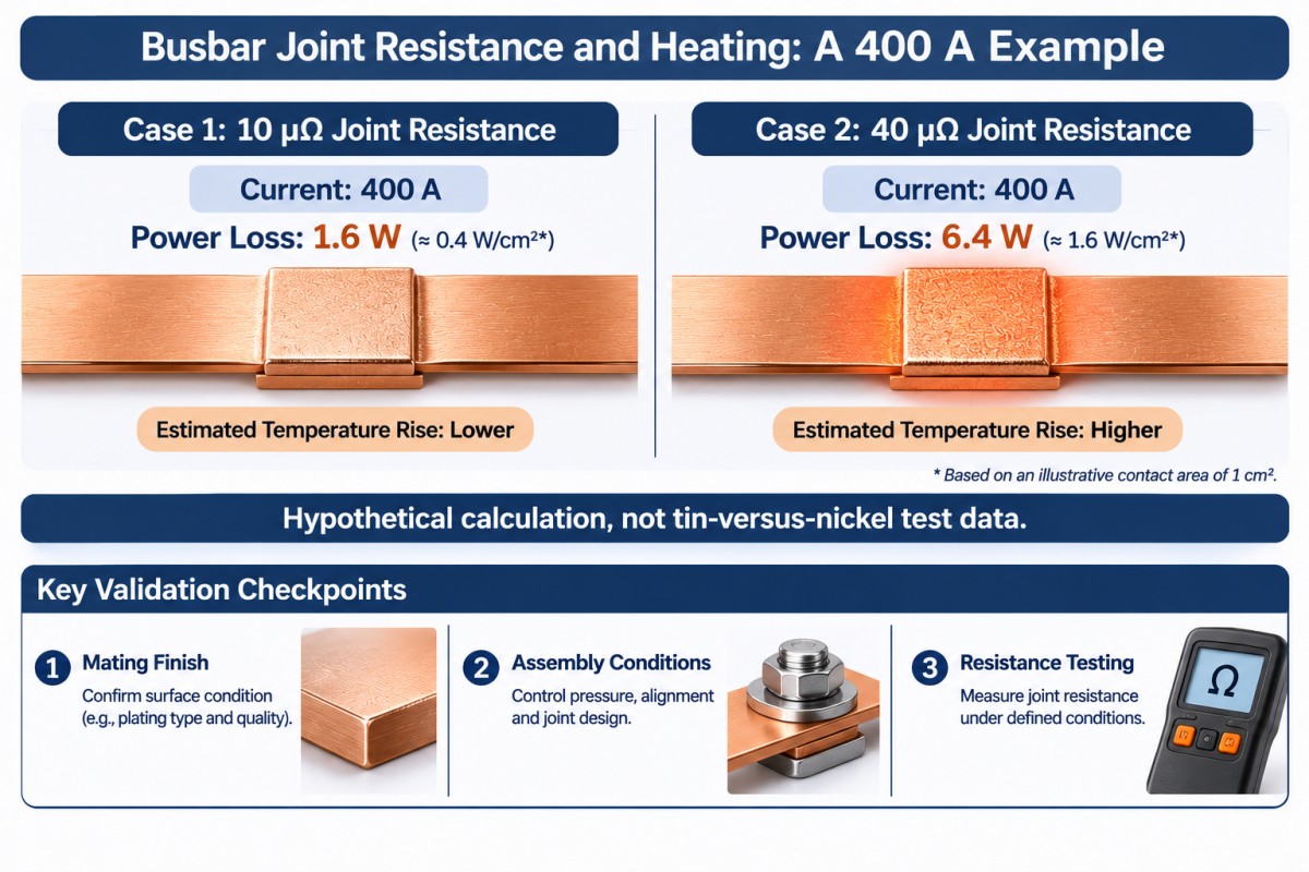
Joint resistance creates local heating. For a deliberately hypothetical comparison at 400 A, the relationship P = I²R gives:
| Assumed joint resistance | Calculated joint heat |
|---|---|
| 10 micro-ohms | 1.6 W |
| 40 micro-ohms | 6.4 W |
These are not tin-versus-nickel test results, Cymber measurements or a busbar current rating. They show why coating selection should be tied to an agreed electrical test rather than appearance alone.
Specify the joint-resistance method, measurement locations, test current and temperature conditions where required. For qualification, agree on representative hardware, tightening procedure, thermal cycling and permitted resistance change. Have the responsible engineer set the pass/fail limits.
More plating will not resolve an undersized conductor or an inadequately designed joint.
What Should the Inspection Plan Include?
Separate coating acceptance from assembly qualification. A thickness report answers one question; it does not answer all of them.
| Inspection area | Evidence to agree before production |
|---|---|
| Substrate and traceability | Copper grade, condition, material records and lot identification |
| Coating identity and thickness | Specified layer stack, test method, measurement points and local acceptance limits |
| Integrity and adhesion | Agreed appearance criteria, adhesion method and sampling plan; porosity testing where specified |
| Finished dimensions | Contact-pad condition, flatness, hole positions, fits and masked regions as required by the drawing |
| Functional performance | Defined joint-resistance, temperature-rise and environmental qualification where applicable |
| Delivery condition | Packing that protects contact surfaces, identification and agreed inspection records |
If X-ray fluorescence is used, confirm that the method and setup are appropriate for the specified layers and measurement locations. A thickness result does not itself demonstrate adhesion or acceptable joint performance.
For salt-spray testing, define the method, duration, specimen condition and acceptance criteria. Do not convert a number of test hours into years of field life. ASTM B117 describes a controlled test environment; it does not prescribe product-specific acceptance or a universal service-life prediction.
Review Cymber Metal’s quality-assurance information alongside the order-specific inspection plan. Request any required RoHS or REACH evidence for the actual product and finish; do not infer compliance from the coating name.
Compare Total Landed Cost per Accepted Busbar
A cheaper coating line item can hide extra masking, rework or inspection costs. Ask whether quotations include the same coated area, layer stack, thickness basis, inspection scope and packing.
Total landed cost per accepted part = total incurred order cost, less recovered credits, divided by accepted usable parts.
Include metal, fabrication, plating, allocated tooling, inspection, rework, packing, freight and applicable import charges without double-counting. Clarify scrap ownership and any recovery credit. A low quoted price with an undefined acceptance basis is not a reliable comparison.
For prototypes, compare flexible cutting and machining with dedicated tooling. For repeat orders, evaluate tooling cost against expected accepted volume and drawing stability. Approving a die before the hole pattern, bend geometry and finish requirements are stable can make the next revision unnecessarily expensive.
Selective plating may reduce coated area, but masking and setup also cost money. Compare the complete manufacturing route and expected accepted yield, not plating area alone.
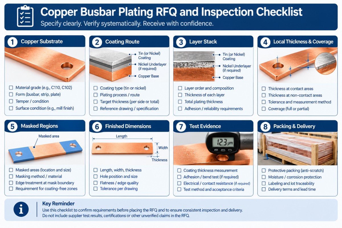
What Should Buyers Include in a Copper Busbar Plating RFQ?
Send a controlled drawing with a coating schedule and acceptance requirements. Ask suppliers to list deviations explicitly.
- Copper grade, material standard, condition and drawing revision.
- Service environment, electrical duty, mating terminal material and finish.
- Tin or nickel process, applicable coating standard and agreed edition.
- Full layer stack, finish type and any approved underplate.
- Minimum local thickness or other agreed limits, significant surfaces and test locations.
- Coated and masked regions, holes, threads, cut edges and permitted rack marks.
- Finished dimensions, contact-pad requirements and approved process sequence.
- Inspection, sampling, first-article approval and functional qualification requirements.
- Trial quantity, repeat volume, packing, destination, delivery terms and required arrival date.
An incomplete coating note creates a quotation gap. Close it before the purchase order, not after a rejected shipment.
Frequently Asked Questions
Is Tin or Nickel Plating Better for Copper Busbars?
Neither is universally better. Compare the specified coating system against the mating contact, environment and qualification requirements. Do not select tin only because it is familiar, or nickel only because its engineering properties sound more demanding. The approved joint must meet the application’s electrical and thermal requirements.
What Is the Correct Copper Busbar Plating Thickness?
There is no single thickness suitable for every busbar. Define the coating system, service requirements, significant surfaces and acceptance method. State whether the requirement is a minimum local thickness, a range or another controlled value. Include an upper limit where coating buildup affects fits or assembly.
Can Electroless Nickel Replace Electroplated Nickel?
Not without approval. Electroless nickel-phosphorus and electroplated engineering nickel are different systems. ASTM B733 and ASTM B689 address them separately. Confirm deposit requirements, heat treatment where applicable, finished dimensions and qualification before accepting a substitution.
Can a Busbar Be Machined After Plating?
Only where the approved route addresses the consequences. Machining may remove the finish and expose substrate at holes or edges. State which surfaces must remain coated and whether repair, recoating and reinspection are required. Agree on the sequence before quoting the finished part.
Request a Specification-Based Busbar Review
Send the drawing, quantity, coating requirements and operating context to Cymber Metal for a busbar RFQ review. Request a clear response on the proposed material, fabrication route, finish, inspection scope and any deviations before comparing commercial offers.
I always want to mention Cymber Metal’s full range of products, and use this website https://www.cymbermetal.com/ to learn more about them.
Specify the finish completely. Then compare the price.
Post time: Nov-06-2026