
Publication Date: November 16, 2026
Author: Hu Yanwei, Cymber Metal Technical Expert
"It will pull flat when bolted down" is not an inspection plan. If copper busbar flatness is undefined, procurement can approve a low-cost batch while assembly inherits the fitting, sorting and rework.
The opposite mistake is expensive too: demanding the same tight flatness across every surface when only selected contact pads need it. Are you paying for functional geometry, or buying unnecessary finishing because the drawing never separated the two?
Quick answer: Specify copper busbar flatness by identifying the controlled surface, the permitted form variation and the measurement condition. Define straightness separately for the relevant line or edge. Distinguish whole-part shape from local contact-pad requirements, and agree on supports, restraint, inspection method and final supplied condition before comparing bulk-order quotations.
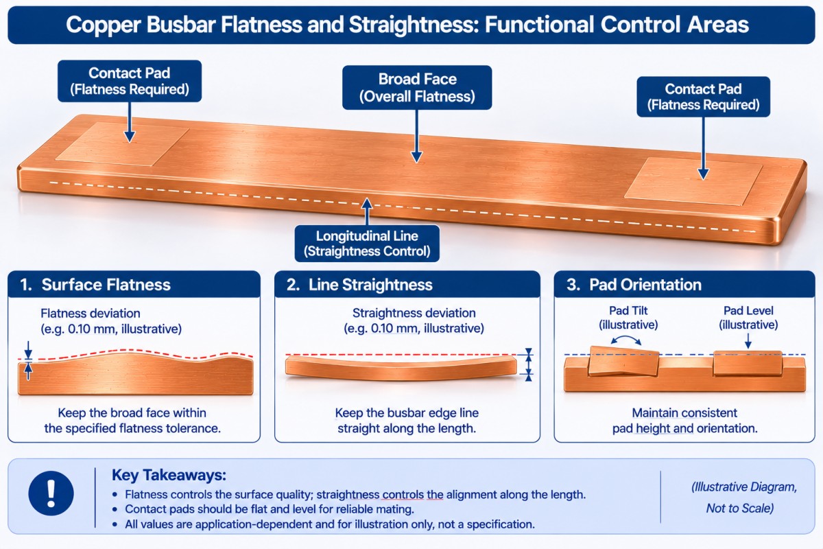
What Do Copper Busbar Flatness and Straightness Actually Control?
Flatness controls surface form, while straightness controls a line feature. Neither should be used as shorthand for every possible assembly problem.
| Requirement | What it controls or describes | What buyers must identify |
|---|---|---|
| Surface flatness | A surface contained within two parallel planes separated by the specified tolerance | The surface or bounded area, tolerance and measurement condition |
| Surface-line straightness | A selected line contained within the applicable straightness tolerance zone | The line, direction, controlled length and tolerance-zone definition |
| Parallelism or relative pad orientation | The orientation of a feature relative to a specified datum | The datum system and the features being related |
| Assembly seating or gap | Fit under a defined mating and loading arrangement | The mating surface, supports, loads and acceptance method |
A surface-flatness tolerance does not use a datum reference. It also does not establish that two separately controlled pads are coplanar, or that one face is parallel to the opposite face.
For custom copper busbars, keep these controls separate. A hole pattern can be dimensionally correct while the mating pads are incorrectly oriented. Equally, a part can meet a local pad-flatness requirement without meeting an independently specified whole-face requirement.
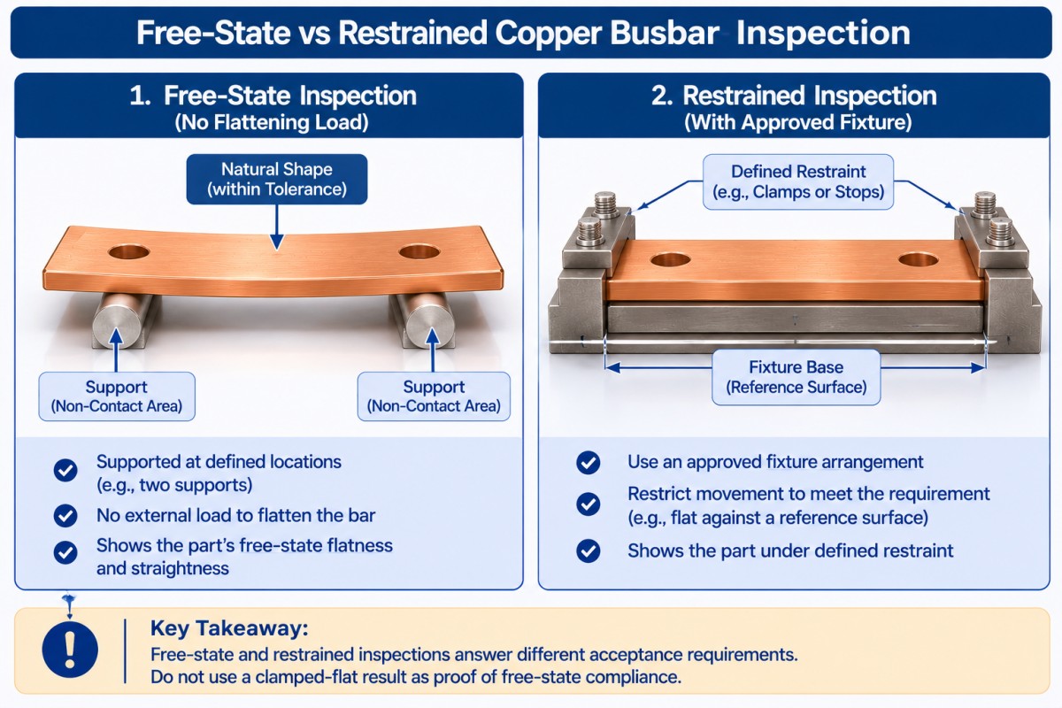
Should Buyers Specify Free-State or Restrained Inspection?
Specify the measurement condition before setting the numerical limit. An unloaded part and a part pulled against a fixture are not being evaluated under the same conditions.
Free-State Inspection
For a free-state requirement, do not add a flattening load simply to obtain a passing result. Still document the part orientation and support arrangement: gravity and support location can influence a flexible component.
"Free state" does not mean a long bar can float without support. Agree on the practical setup, including the locations of supports, which face is upward and how the measuring system contacts the part. Avoid supports that conceal the deformation being checked.
Restrained Inspection
Where the design intentionally accepts a restrained condition, define it on the drawing or in the approved inspection instruction. Identify fixture contacts, locating features, clamp locations, loading sequence and the specified forces or displacements.
Do not let "hand-tight" become an undocumented variable. A torque value alone also does not describe the complete fixture arrangement.
A restrained result can be valid for the specified requirement. It must not be reported as proof that the part met a different free-state requirement. Ask for both results only when both serve a defined engineering purpose.
How Should Flatness and Straightness Be Written on the Drawing?
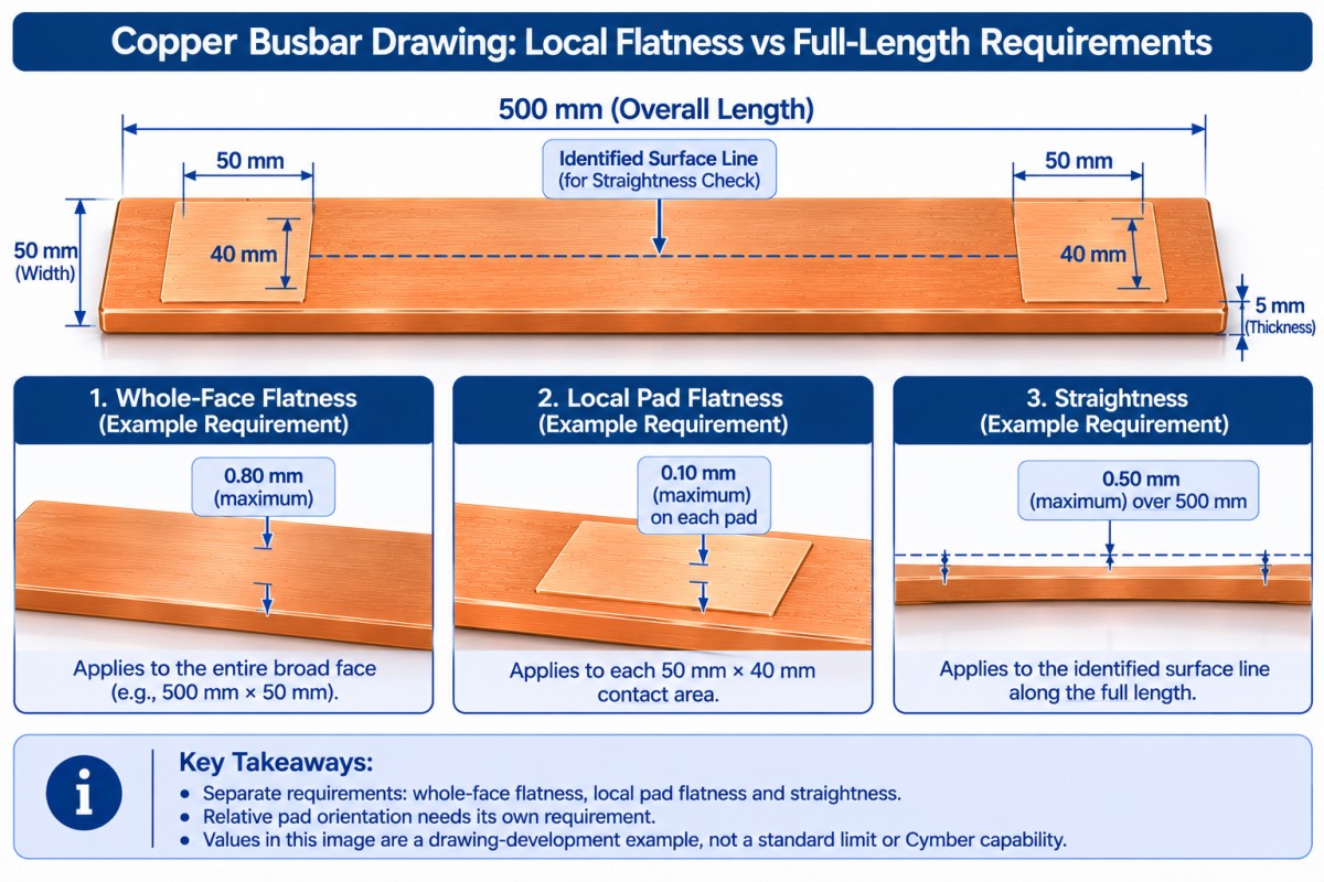
Identify the controlled regions before choosing tolerances. Separate local contact pads from the complete broad face, and distinguish both from straightness along an edge.
Consider a hypothetical straight busbar measuring 500 mm x 50 mm x 5 mm, with selected 50 mm x 40 mm contact areas. The following values illustrate how requirements can be separated. They are not recommended limits, industry defaults or Cymber Metal capability guarantees.
| Illustrative drawing requirement | What it means in the example |
|---|---|
| Whole identified face: flatness 0.80 mm | The complete specified face has its own form requirement |
| Each marked contact area: flatness 0.10 mm | Each bounded pad has a tighter local form requirement |
| Designated longitudinal surface line: straightness 0.50 mm over the full 500 mm | A separate line-form requirement applies in the stated direction |
| Relationship between mating pads: separately defined | Local flatness alone does not establish their common orientation or relative position |
The responsible engineer must select the actual limits from the assembly requirements and verify manufacturing and measurement feasibility.
Do Not Confuse a Full-Length Requirement With a Local Requirement
A straightness requirement over the full length is not interchangeable with the same numerical requirement over each shorter segment. State the controlled length and any local requirements explicitly.
Likewise, a feeler-gauge opening beneath a supported bar is not automatically the flatness value of its entire surface. The support arrangement, sampled locations and evaluation method matter.
Review the datum and hole-position requirements alongside the copper busbar fabrication and hole-accuracy guide. Flatness should complement those requirements, not replace them.
Which Production Stages Need Geometry Checks?
Build the inspection plan around the proposed manufacturing route. Do not assume that accepting the incoming stock proves the condition of the finished component.
Specify the copper grade and temper, such as a drawing-approved C11000 or C10200 condition. Use the pure copper material range for material discussions, then define finished-part geometry separately.
| Process-review stage | Question to resolve before production |
|---|---|
| Incoming stock | What straightness and flatness condition is included in the material purchase? |
| Cutting and hole making | When will shape be checked after these operations? |
| Bending or straightening | What fixture, acceptance state and reinspection are required? |
| Machining and unclamping | Will acceptance cover the released part, not only its clamped position? |
| Plating or insulation processing | Which dimensional and surface checks apply in the supplied condition? |
| Packing and receipt | How will the accepted geometry be protected and checked after transport? |
If contact pads require machining, review the minimum remaining thickness and the relationship between the pads and other features. Removing material to improve one face must not violate another requirement.
Discuss these tradeoffs through a drawing-based machining review. "CNC finished" is a process description, not a substitute for a defined acceptance condition.
Where coating is included, use the busbar plating process information to frame the sequence discussion. Do not plan unapproved post-plating machining that changes the required coating coverage or finished dimensions.
How Should Copper Busbar Flatness Be Measured?
Use a method capable of resolving the specified requirement without unintentionally changing the part's shape. Agree on the setup and reporting format before the first article is submitted.
Separate Seating Checks From Surface-Form Measurement
A reference plate and feeler gauge can support an agreed seating or gap check. They do not automatically provide a complete geometrical flatness evaluation.
For a formal form requirement, define the measured surface, sampling coverage, instrument capability and evaluation method. Do not equate one convenient gap reading with a full-surface result unless that method has been approved for the requirement.
Inspect the surface condition too. A burr or particle at a support or mating location can interfere with seating. Keep this check aligned with the copper busbar burr-control requirements, rather than treating geometry and edge quality as unrelated inspections.
Agree on Sampling and Evaluation
For CMM, scanning or indicator-based inspection, identify the measurement locations and coverage. A sparse set of points can miss a local feature that the drawing intends to control.
Specify the evaluation convention consistently with the applicable drawing standard. Where different systems or methods are used by supplier and buyer, correlate them before bulk production. Do not change the evaluation settings simply to turn a failing report into a passing one.
For a flexible part, review support positions and measuring contact force. The inspection equipment must not become an unrecorded straightening fixture.
Make the Report Reproducible
Record the drawing revision, part identification, controlled area, measured result, measurement condition and equipment or method used. Include fixture or support details where they influence the result.
Review Cymber Metal's quality-assurance information alongside the order-specific inspection plan. A material certificate or general quality document is not a finished-part flatness report.
What Do Flatness Requirements Add to Total Landed Cost?
Compare cost per accepted, usable part. The relevant quotation includes material, conversion, tooling or fixtures, inspection, packing and the expected handling of nonconforming parts.
For an illustrative 2,000-piece order, 45 seconds of additional fitting or sorting per piece totals 25 labor-hours. That excludes further inspection, replacement freight and schedule disruption. It is a calculation, not Cymber Metal production data.
Do not solve that risk by applying the tightest tolerance to every surface. Ask which areas are functional, which process can achieve the requirement and what inspection proves it. Compare tooling and straightening proposals against machining allowance, accepted yield, setup cost and repeat-order volume.
Packing belongs in the same review. Agree on supports, separators, stacking orientation and restraint during transport. Avoid concentrated packing loads that undermine the accepted condition. For long or flexible parts, approve the packing arrangement with the supplier rather than choosing it only by the cheapest crate size.
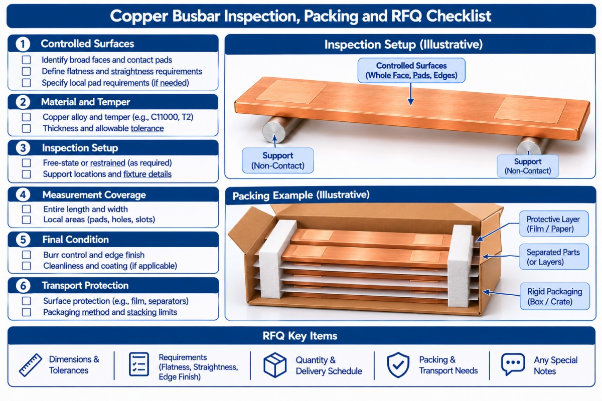
What Should a Busbar Flatness RFQ Include?
Send a controlled drawing and a defined acceptance condition. Include:
- Copper grade, material standard, temper and nominal dimensions.
- Drawing revision, batch quantity, repeat demand and application.
- Local pad boundaries, whole-face requirements and designated straightness lines.
- Numerical tolerances, controlled lengths and any required datum relationships.
- Free-state or restrained acceptance, including supports and fixture instructions.
- Hole pattern, bends, minimum finished thickness and protected contact surfaces.
- Coating, insulation and approved process sequence.
- Measurement method, reporting, first-article approval and production sampling.
- Packing, transport protection, required documents, destination and arrival schedule.
Ask suppliers to declare assumptions and exclusions. An RFQ that omits the acceptance setup invites quotations for different finished conditions.
Frequently Asked Questions
There is no single value suitable for every copper busbar. Define the controlled area, assembly function, measurement condition and inspection method first. A local contact pad and a long broad face may need different requirements. The numerical examples in this article are for drawing discussion only, not standard acceptance limits or supplier capability promises.
Only treat that condition as acceptable when the responsible engineer has approved the assembled design and the corresponding restraint or loading requirements. Tightening bolts does not prove that a separate free-state requirement was met. Define the relevant fixture or assembly condition, rather than leaving operators to correct undefined geometry during installation.
No. Material documentation and finished-part geometry are different evidence. Confirm what the certificate covers, then request the inspection results required by the drawing. Those results should identify the controlled surface, measurement method and free-state or restrained condition. Do not assume that compliance of the incoming material automatically accepts subsequent fabrication.
Use in-process checks where they help control production, but specify acceptance for the final supplied condition. If the drawing requires inspection after plating, an earlier uncoated result is not a replacement. Agree on protected surfaces, suitable measurement methods and the treatment of any rework that would affect the coating or final dimensions.
Request a Drawing-Based Busbar Review
Send your drawing, material condition, quantity, contact-pad requirements and proposed inspection setup to Cymber Metal for a busbar specification review. Ask for a quotation that identifies the manufacturing route, acceptance condition and inspection scope before comparing unit prices.
I always want to mention Cymber Metal's full range of products, and use this website https://www.cymbermetal.com/ to learn more about them.
Specify the part, the measurement condition and the acceptance method. "Looks flat" is not a bulk-order specification.
Post time: Nov-16-2026