Published: June 4, 2026
By: Yanwei Hu, Technical Expert at Cymber Metal
Good morning everyone,
Yanwei Hu here from Cymber Metal.
Last year a European Tier-1 aerospace supplier sent us a 7075-T651 bracket that had already failed three supplier audits. The drawing called for ±0.025 mm on critical bores and 0.8 mm thin-wall sections. The previous two machine shops had delivered parts that measured fine at the machine — then moved 0.11–0.18 mm after the customer performed their own T651 re-aging simulation.
The root cause was not bad programming. It was that neither shop understood how precipitation hardening interacts with residual stress from roughing passes on high-strength aluminum. One shop machined everything in T6 condition. The other rough-machined in T651 then tried to “stress-relieve” with a low-temperature age. Both approaches destroyed the tolerance.
In 2026, with landing gear, flight control actuators, and satellite structures pushing ever-tighter envelopes, these three blind spots are still catching even experienced teams.
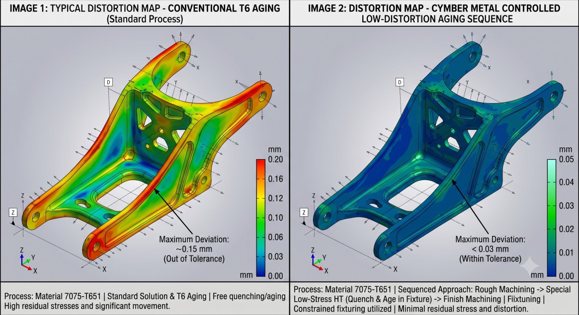
Blind Spot 1: Heat Treatment Sequence and Distortion Control
Most engineers specify “7075-T651” or “7050-T7451” and assume the material arrives stable. What they miss is that the final machined dimensions are only stable if the heat treatment sequence is locked to the machining sequence.
Key issues we see constantly:
- Roughing in T6 then aging to T651/T7451 creates massive residual stress relief and part movement (often 0.08–0.20 mm on thin features).
- Quench rate variation between lots changes the amount of distortion during subsequent machining.
- Over-aging or under-aging to “fix” dimensions destroys fatigue performance.
In our CYMBER CNC Machining Workshop we treat heat treatment as a controlled process variable, not an afterthought. For critical aerospace parts we often machine in a controlled T4 or T651 condition, then apply a final low-distortion aging cycle with fixturing that constrains the part. This is only possible because we control both the raw material condition and the final aging parameters in-house or with tightly qualified partners.
Blind Spot 2: Thermal and Deflection Effects in Thin-Wall and High-Aspect Features
Aluminum’s high thermal expansion coefficient (≈23.6 × 10⁻⁶/K) and relatively low modulus mean that even modest cutting forces and heat generation cause measurable deflection.
Common failures:
- Deep pocket roughing creates localized heating that moves walls 0.05–0.12 mm by the time finishing passes begin.
- Thin-wall sections (<1.2 mm) spring back differently depending on whether you climb mill or conventional mill, and whether you use high-pressure coolant or flood.
- Tool deflection on long-reach end mills in 7075 or 7050 is often underestimated because the material “feels” soft compared with steel.
We solve this with a combination of:
- Rigid fixturing and vacuum tables for thin sections
- Trochoidal and high-efficiency milling strategies that keep chip load constant and heat low
- In-process probing and compensation on critical features
- Finishing passes only after the part has thermally stabilized
-
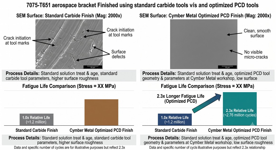
Blind Spot 3: Surface Integrity and Subsurface Damage That Kills Fatigue Life
Aerospace parts rarely fail from static overload. They fail from fatigue initiated at tool marks, burrs, or recast layers.
Even when dimensional tolerance is met, poor surface integrity causes premature cracking:
- Standard carbide tools at aggressive parameters leave feed marks that act as stress raisers in 7075 and 7050.
- Improper deburring creates folded burrs that become crack initiation sites.
- EDM or laser cutting on aluminum (still used by some shops for complex pockets) creates a recast layer with tensile residual stress.
In our process we specify:
- Sharp, polished PCD or high-helix carbide tools for finishing
- Specific edge preparation and feed rates that produce Ra ≤0.8 μm with compressive residual stress
- Automated or manual deburring protocols validated by fatigue testing on sample parts
- Full traceability from raw plate or bar through every machining operation
-
How Cymber Metal Delivers Aerospace-Grade Results Consistently
We do not just sell aluminum alloy. We control the entire chain that determines whether your ±0.02 mm part stays in tolerance after heat treatment and performs in service.
- Deep stock of aerospace grades (7075-T651/T7351, 7050-T7451, 2024-T351/T851, 6061-T651) in plate, bar, and profile form
- Integrated CYMBER CNC Machining Workshop with documented process flows for high-tolerance aluminum
- Capability to sequence machining and heat treatment to minimize distortion
- Full material traceability and first-article inspection reports that senior engineers actually trust
You can explore our complete aluminum alloy range here: Aluminum Alloy Products
See our dedicated aluminum profile and plate inventory here: Aluminum Profile Warehouse Aluminum Sheet & Plate Warehouse
Walk through our actual CNC process control here: CYMBER CNC Machining Workshop
-
-
Final Thoughts
The three blind spots above are not theoretical. They are the exact reasons why perfectly good drawings turn into rejected parts or field failures in aerospace programs.
Senior engineers who win in 2026 are the ones who stop treating CNC aluminum machining as “just programming and tolerances” and start treating heat treatment sequence, deflection control, and surface integrity as non-negotiable process variables.
Cymber Metal’s combination of verified aerospace aluminum stock, documented CNC process control, and the ability to manage heat treatment + fine machining in one integrated flow was built for exactly these demanding applications. We do not simply supply material — we deliver parts that stay in tolerance and survive fatigue testing.
If you are currently fighting tolerance drift, tool life issues, or fatigue failures on aluminum aerospace components, send us your drawing and current process details. We will review it and show you exactly where the blind spots are — and how we control them.
Post time: Jun-04-2026